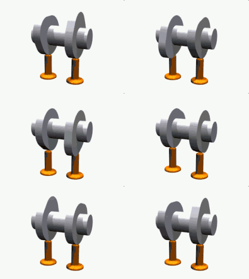

A cam is a rotating or sliding piece in a mechanical linkage used especially in transforming rotary motion into linear motion.[1][2] It is often a part of a rotating wheel (e.g. an eccentric wheel) or shaft (e.g. a cylinder with an irregular shape) that strikes a lever at one or more points on its circular path. The cam can be a simple tooth, as is used to deliver pulses of power to a steam hammer, for example, or an eccentric disc or other shape that produces a smooth reciprocating (back and forth) motion in the follower, which is a lever making contact with the cam. A cam timer is similar, and were widely used for electric machine control (an electromechanical timer in a washing machine being a common example) before the advent of inexpensive electronics, microcontrollers, integrated circuits, programmable logic controllers and digital control.
Camshaft
The cam can be seen as a device that converts rotational motion to reciprocating (or sometimes oscillating) motion.[3] A common example is the camshaft of an automobile, which takes the rotary motion of the engine and converts it into the reciprocating motion necessary to operate the intake and exhaust valves of the cylinders.
Displacement diagram
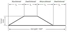
Cams can be characterized by their displacement diagrams, which reflect the changing position a follower would make as the surface of the cam moves in contact with the follower. In the example shown, the cam rotates about an axis. These diagrams relate angular position, usually in degrees, to the radial displacement experienced at that position. Displacement diagrams are traditionally presented as graphs with non-negative values. A simple displacement diagram illustrates the follower motion at a constant velocity rise followed by a similar return with a dwell in between as depicted in figure 2.[4] The rise is the motion of the follower away from the cam center, dwell is the motion where the follower is at rest, and return is the motion of the follower toward the cam center.[5]
A common type is in the valve actuators in internal combustion engines. Here, the cam profile is commonly symmetric and at rotational speeds generally met with, very high acceleration forces develop. Ideally, a convex curve between the onset and maximum position of lift reduces acceleration, but this requires impractically large shaft diameters relative to lift. Thus, in practice, the points at which lift begins and ends mean that a tangent to the base circle appears on the profile. This is continuous with a tangent to the tip circle. In designing the cam, the lift and the dwell angle θ are given. If the profile is treated as a large base circle and a small tip circle, joined by a common tangent, giving lift L, the relationship can be calculated, given the angle φ between one tangent and the axis of symmetry (φ being π/2 − θ/2), while C is the distance between the centres of the circles (required), and R is the radius of the base (given) and r that of the tip circle (required):
- C = L/1 − sin φ and r = R − L sin φ/1 − sin φ
Disc or plate cam
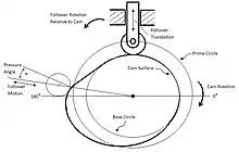
The most commonly used cam is the cam plate (also known as disc cam or radial cam[6]) which is cut out of a piece of flat metal or plate.[7] Here, the follower moves in a plane perpendicular to the axis of rotation of the camshaft.[8] Several key terms are relevant in such a construction of plate cams: base circle, prime circle (with radius equal to the sum of the follower radius and the base circle radius), pitch curve which is the radial curve traced out by applying the radial displacements away from the prime circle across all angles, and the lobe separation angle (LSA – the angle between two adjacent intake and exhaust cam lobes).
The base circle is the smallest circle that can be drawn to the cam profile.
A once common, but now outdated, application of this type of cam was automatic machine tool programming cams. Each tool movement or operation was controlled directly by one or more cams. Instructions for producing programming cams and cam generation data for the most common makes of machine, were included in engineering references well into the modern CNC era.[9]
This type of cam is used in many simple electromechanical appliances controllers, such as dishwashers and clothes washing machines, to actuate mechanical switches that control the various parts.
Cylindrical cam

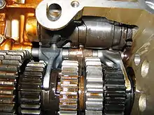
A cylindrical cam or barrel cam is a cam in which the follower rides on the surface of a cylinder. In the most common type, the follower rides in a groove cut into the surface of a cylinder. These cams are principally used to convert rotational motion to linear motion perpendicular to the rotational axis of the cylinder. A cylinder may have several grooves cut into the surface and drive several followers. Cylindrical cams can provide motions that involve more than a single rotation of the cylinder and generally provide positive positioning, removing the need for a spring or other provision to keep the follower in contact with the control surface.
Applications include machine tool drives, such as reciprocating saws, and shift control barrels in sequential transmissions, such as on most modern motorcycles.
A special case of this cam is a constant lead, where the position of the follower is linear with rotation, as in a lead screw. The purpose and detail of implementation influence whether this application is called a cam or a screw thread, but in some cases, the nomenclature may be ambiguous.
Cylindrical cams may also be used to reference an output to two inputs, where one input is the rotation of the cylinder and the other is the position of the follower along the cam. The output is radial to the cylinder. These were once common for special functions in control systems, such as fire control mechanisms for guns on naval vessels[10] and mechanical analog computers.[11]
An example of a cylindrical cam with two inputs is provided by a duplicating lathe, an example of which is the Klotz axe handle lathe,[12] which cuts an axe handle to a form controlled by a pattern acting as a cam for the lathe mechanism.
Face cam
A face cam produces motion by using a follower riding on the face of a disk. The most common type has the follower ride in a slot so that the captive follower produces radial motion with positive positioning without the need for a spring or other mechanism to keep the follower in contact with the control surface. A face cam of this type generally has only one slot for a follower on each face. In some applications, a single element, such as a gear, a barrel cam or other rotating element with a flat face, may do duty as a face cam in addition to other purposes.
Face cams may provide repetitive motion with a groove that forms a closed curve or may provide function generation with a stopped groove. Cams used for function generation may have grooves that require several revolutions to cover the complete function, and in this case, the function generally needs to be invertible so that the groove does not self intersect, and the function output value must differ enough at corresponding rotations that there is sufficient material separating the adjacent groove segments. A common form is the constant lead cam, where the displacement of the follower is linear with rotation, such as the scroll plate in a scroll chuck. Non-invertible functions, which require the groove to self-intersect, can be implemented using special follower designs.
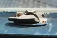
A variant of the face cam provides motion parallel to the axis of cam rotation. A common example is the traditional sash window lock, where the cam is mounted to the top of the lower sash, and the follower is the hook on the upper sash. In this application, the cam is used to provide a mechanical advantage in forcing the window shut, and also provides a self-locking action, like some worm gears, due to friction.
Face cams may also be used to reference a single output to two inputs, typically where one input is the rotation of the cam and the other is the radial position of the follower. The output is parallel to the axis of the cam. These were once common is mechanical analog computation and special functions in control systems.[13]
A face cam that implements three outputs for a single rotational input is the stereo phonograph, where a relatively constant lead groove guides the stylus and tonearm unit, acting as either a rocker-type (tonearm) or linear (linear tracking turntable) follower, and the stylus alone acting as the follower for two orthogonal outputs to representing the audio signals. These motions are in a plane radial to the rotation of the record and at angles of 45 degrees to the plane of the disk (normal to the groove faces). The position of the tonearm was used by some turntables as a control input, such as to turn the unit off or to load the next disk in a stack, but was ignored in simple units.
Heart shaped cam
This type of cam, in the form of a symmetric heart, is used to return a shaft holding the cam to a set position by pressure from a roller. They were used on early models of Post Office Master clocks to synchronise the clock time with Greenwich Mean Time when the activating follower was pressed onto the cam automatically via a signal from an accurate time source.[14]
Snail drop cam
This type of cam was used for example in mechanical timekeeping clocking-in clocks to drive the day advance mechanism at precisely midnight and consisted of a follower being raised over 24 hours by the cam in a spiral path which terminated at a sharp cut off at which the follower would drop down and activate the day advance. Where timing accuracy is required as in clocking-in clocks these were typically ingeniously arranged to have a roller cam follower to raise the drop weight for most of its journey to near its full height, and only for the last portion of its travel for the weight to be taken over and supported by a solid follower with a sharp edge. This ensured that the weight dropped at a precise moment, enabling accurate timing.[15] This was achieved by the use of two snail cams mounted coaxially with the roller initially resting on one cam and the final solid follower on the other but not in contact with its cam profile. Thus the roller cam initially carried the weight, until at the final portion of the run the profile of the non-roller cam rose more than the other causing the solid follower to take the weight.
Linear cam
A linear cam is one in which the cam element moves in a straight line rather than rotates. The cam element is often a plate or block but may be any cross-section.[16] The key feature is that the input is a linear motion rather than rotational. The cam profile may be cut into one or more edges of a plate or block, may be one or more slots or grooves in the face of an element, or may even be a surface profile for a cam with more than one input. The development of a linear cam is similar to, but not identical to, that of a rotating cam.[17]
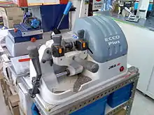
A common example of a linear cam is a key for a pin tumbler lock. The pins act as followers. This behavior is exemplified when the key is duplicated in a key duplication machine, where the original key acts as a control cam for cutting the new key.
History
Cam mechanisms appeared in China at around 600 BC in the form of a crossbow trigger-mechanism with a cam-shaped swing arm.[18] However, the trigger mechanism did not rotate around its own axis and traditional Chinese technology generally made little use of continuously rotating cams.[19] Nevertheless, later research showed that such cam mechanisms did in fact rotate around its own axis.[20] Likewise, more recent research indicates that cams were used in water-driven trip hammers by the latter half of the Western Han Dynasty (206 BC – 8 AD) as recorded in the Huan Zi Xin Lun. Complex pestles were also mentioned in later records such as the Jin Zhu Gong Zan and the Tian Gong Kai Wu, amongst many other records of water-driven pestles.[21] During the Tang dynasty, the wooden clock within the water-driven astronoical device, the spurs inside a water-driven armillary sphere, the automated alarm within a five-wheeled sand-driven clock, artificial paper figurines within a revolving lantern, all utilized cam mechanisms.[22] The Chinese hodometer which utilized a bell and gong mechanism is also a cam, as described in the Song Shi. In the book Nongshu, the vertical wheel of a water-driven wind box is also a cam.[23] Out of these examples, the water-driven pestle and the water driven wind box both have two cam mechanisms inside.[24] Cams that rotated continuously and functioned as integral machine elements were built into Hellenistic water-driven automata from the 3rd century BC.[25] The cam and camshaft later appeared in mechanisms by Al-Jazari and Shooshtari, who used them in their automata, described in 1206.[26] The cam and camshaft appeared in European mechanisms from the 14th century.[27] Waldo J Kelleigh of Electrical Apparatus Company patented the adjustable cam[28] in the United States in 1956 for its use in mechanical engineering and weaponry.
See also
- Reciprocating motion – Repetitive back-and-forth linear motion
- Cam engine – Reciprocating engine where the pistons drive a cam actuated shaft
- Swashplate – Mechanism to convert between reciprocating and rotary motion
- Crank (mechanism) – Simple machine transferring motion to or from a rotating shaft at a distance from the centreline
- Eccentric (mechanism) – Circular disk rigidly fixed to a rotating axle with its center offset from that of the axle
References
- ↑ "cam definition". Merriam Webster. Retrieved 2010-04-05.
a rotating or sliding piece (as an eccentric wheel or a cylinder with an irregular shape) in a mechanical linkage used especially in transforming rotary motion into reciprocating motion or vice versa
- ↑ Shigley, J.; Uicker, J. (2010). Cam Design. Theory of Machines and Mechanisms (4 ed.). Oxford University Press, USA. p. 200.
- ↑ Jensen, Preddben w. (1965). Cam Design and Manufacture. The Industrial Press, New York. p. 1. ISBN 9780824775124.
- ↑ Cam Design and Manufacture. The Industrial Press, New York. p. 8.
- ↑ Introduction to Mechanisms – Cams"rise is the motion of the follower away from the cam center, dwell is the motion where the follower is at rest, and return is the motion of the follower toward the cam center"
- ↑ "Cams; their profiles and the velocity and acceleration of their associated followers". Retrieved 29 August 2013.
- ↑ Jensen, Preben w. (1965). Cam Design and Manufacture. The Industrial Press, New York. p. 1.
- ↑ Introduction to Mechanisms – Cams "The follower moves in a plane perpendicular to the axis of rotation of the camshaft."
- ↑ Oberg, Erik (1996). Machinery's Handbook, 25th Ed. Industrial Press. pp. 1050–1055.
- ↑ Bomar; Null; Wallace (1996). Gunners Mate 1 & C NAVEDTRA 14110. Naval Education and Training Professional Development and Technology Center. pp. 4–2.
- ↑ Clymer, A. Ben (1993). "The Mechanical Analog Computers of Hannibal Ford and William Newell". IEEE Annals of the History of Computing. 15 (2): 19–34. doi:10.1109/85.207741. S2CID 6500043.
- ↑ House handles Klotz lathe on YouTube
- ↑ Bomar, Null, and Wallace (1996). Gunners Mate 1 & C NAVEDTRA 14110. Naval Education and Training Professional Development and Technology Center. pp. 4–1.
{{cite book}}: CS1 maint: multiple names: authors list (link) - ↑ Motion of heart-shaped cam
- ↑ Motion of snail drop cam
- ↑ "Linear cam mechanical interlock".
- ↑ "Calculation equations:cams". Retrieved 29 August 2013.
- ↑ Kuo-Hung Hsiao; Hong-SenYan (2014). "Mechanisms in Ancient Chinese Books with Illustrations". Springer International Publishing: 70–71.
{{cite journal}}: Cite journal requires|journal=(help) - ↑ Joseph Needham: Science and Civilisation in China, Volume 4: Physics and Physical Technology, Part II: mechanical Engineering, Cambridge University Press, 1965, p. 84
- ↑ Kuo-Hung Hsiao (2013). "Structural Synthethis of Ancient Chinese Original Crossbow": 270.
{{cite journal}}: Cite journal requires|journal=(help) - ↑ Hsiao(2014) p71.
- ↑ Hsiao(2014) p71.
- ↑ Hsiao(2014) p71.
- ↑ Hsiao(2014) p71.
- ↑ Lewis, M. J. T. (1997), Millstone and Hammer. The Origins of Water Power, The University of Hull Press, pp. 84–88, ISBN 0-85958-657-X
- ↑ Georges Ifrah (2001). The Universal History of Computing: From the Abacus to the Quantum Computer (PDF). Translated by E.F. Harding. John Wiley & Sons, Inc. p. 171. Archived from the original (PDF) on October 8, 2006.
- ↑ A. Lehr (1981). De Geschiedenis van het Astronomisch Kunstuurwerk. Den Haag. p. 227. Archived from the original on October 25, 2010.
- ↑ "Cam Patent".
External links
- Cam design pages Creates animated cams for specified follower motions.
- Kinematic Models for Design Digital Library (KMODDL) – Movies and photos of hundreds of working mechanical-systems models at Cornell University. Also includes an e-book library of classic texts on mechanical design and engineering.
- Introduction to Mechanisms – Cams Classification, nomenclature, motion, and design of cams; information for the course, Introduction to Mechanisms, at Carnegie Mellon University.
- Polynomial cam function with excel VBA file to demonstrate its motion