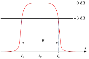
In electrical engineering and telecommunications, the center frequency of a filter or channel is a measure of a central frequency between the upper and lower cutoff frequencies. It is usually defined as either the arithmetic mean or the geometric mean of the lower cutoff frequency and the upper cutoff frequency of a band-pass system or a band-stop system.
Typically, the geometric mean is used in systems based on certain transformations of lowpass filter designs, where the frequency response is constructed to be symmetric on a logarithmic frequency scale.[1] The geometric center frequency corresponds to a mapping of the DC response of the prototype lowpass filter, which is a resonant frequency sometimes equal to the peak frequency of such systems, for example as in a Butterworth filter.
The arithmetic definition is used in more general situations, such as in describing passband telecommunication systems, where filters are not necessarily symmetric but are treated on a linear frequency scale for applications such as frequency-division multiplexing.[2]
References
- ↑ John T. Taylor and Qiuting Huang (1997). CRC Handbook of Electrical Filters. CRC Press. ISBN 0-8493-8951-8.
- ↑ Julie K. Petersen (2003). Fiber Optics Illustrated Dictionary. CRC Press. ISBN 0-8493-1349-X.