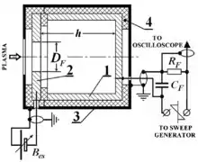
 Schematic diagram of a Faraday cup | |
| Uses | Charged particle detector |
|---|---|
| Related items | Electron multiplier Microchannel plate detector Daly detector |
A Faraday cup is a metal (conductive) cup designed to catch charged particles in vacuum. The resulting current can be measured and used to determine the number of ions or electrons hitting the cup.[1] The Faraday cup was named after Michael Faraday who first theorized ions around 1830.
Examples of devices which use Faraday cups include space probes (Voyager 1, & 2, Parker Solar Probe, etc.) and mass spectrometers.
Principle of operation

When a beam or packet of ions hits the metallic body of the cup, the apparatus gains a small net charge while the ions are neutralized as the charge is transferred to the metal walls. The metal part can then be discharged to measure a small current proportional to the number of impinging ions. The Faraday cup is essentially part of a circuit where ions are the charge carriers in vacuum and it is the interface to the solid metal where electrons act as the charge carriers (as in most circuits). By measuring the electric current (the number of electrons flowing through the circuit per second) in the metal part of the circuit, the number of charges being carried by the ions in the vacuum part of the circuit can be determined. For a continuous beam of ions (each with a single charge), the total number of ions hitting the cup per unit time is
where N is the number of ions observed in a time t (in seconds), I is the measured current (in amperes) and e is the elementary charge (about 1.60 × 10⁻¹⁹ C). Thus, a measured current of one nanoamp (10−9 A) corresponds to about 6 billion ions striking the Faraday cup each second.
Similarly, a Faraday cup can act as a collector for electrons in a vacuum (e.g. from an electron beam). In this case, electrons simply hit the metal plate/cup and a current is produced. Faraday cups are not as sensitive as electron multiplier detectors, but are highly regarded for accuracy because of the direct relation between the measured current and number of ions.
In plasma diagnostics
The Faraday cup utilizes a physical principle according to which the electrical charges delivered to the inner surface of a hollow conductor are redistributed around its outer surface due to mutual self-repelling of charges of the same sign – a phenomenon discovered by Faraday.[2]

The conventional Faraday cup is applied for measurements of ion (or electron) flows from plasma boundaries and comprises a metallic cylindrical receiver-cup – 1 (Fig. 1) closed with, and insulated from, a washer-type metallic electron-suppressor lid – 2 provided with the round axial through enter-hollow of an aperture with a surface area . Both the receiver cup and the electron-suppressor lid are enveloped in, and insulated from, a grounded cylindrical shield – 3 having an axial round hole coinciding with the hole in the electron-suppressor lid – 2. The electron-suppressor lid is connected by 50 Ω RF cable with the source of variable DC voltage . The receiver-cup is connected by 50 Ω RF cable through the load resistor with a sweep generator producing saw-type pulses . Electric capacity is formed of the capacity of the receiver-cup – 1 to the grounded shield – 3 and the capacity of the RF cable. The signal from enables an observer to acquire an I-V characteristic of the Faraday cup by oscilloscope. Proper operating conditions: (due to possible potential sag) and , where is the ion free path. Signal from is the Faraday cup I-V characteristic which can be observed and memorized by oscilloscope
-
(1)
In Fig. 1: 1 – cup-receiver, metal (stainless steel). 2 – electron-suppressor lid, metal (stainless steel). 3 – grounded shield, metal (stainless steel). 4 – insulator (teflon, ceramic). – capacity of Faraday cup. – load resistor.
Thus we measure the sum of the electric currents through the load resistor : (Faraday cup current) plus the current induced through the capacitor by the saw-type voltage of the sweep-generator: The current component can be measured at the absence of the ion flow and can be subtracted further from the total current measured with plasma to obtain the actual Faraday cup I-V characteristic for processing. All of the Faraday cup elements and their assembly that interact with plasma are fabricated usually of temperature-resistant materials (often these are stainless steel and teflon or ceramic for insulators). For processing of the Faraday cup I-V characteristic, we are going to assume that the Faraday cup is installed far enough away from an investigated plasma source where the flow of ions could be considered as the flow of particles with parallel velocities directed exactly along the Faraday cup axis. In this case, the elementary particle current corresponding to the ion density differential in the range of velocities between and of ions flowing in through operating aperture of the electron-suppressor can be written in the form
-
(2)
where
-
(3)
is elementary charge, is the ion charge state, and is the one-dimensional ion velocity distribution function. Therefore, the ion current at the ion-decelerating voltage of the Faraday cup can be calculated by integrating Eq. (2) after substituting Eq. (3),
-
(4)
where the lower integration limit is defined from the equation where is the velocity of the ion stopped by the decelerating potential , and is the ion mass. Thus Eq. (4) represents the I-V characteristic of the Faraday cup. Differentiating Eq. (4) with respect to , one can obtain the relation
-
(5)
where the value is an invariable constant for each measurement. Therefore, the average velocity of ions arriving into the Faraday cup and their average energy can be calculated (under the assumption that we operate with a single type of ion) by the expressions
-
[cm/s]
(6)
-
[eV]
(7)
where is the ion mass in atomic units. The ion concentration in the ion flow at the Faraday cup vicinity can be calculated by the formula
-
(8)
which follows from Eq. (4) at ,
-
(9)

and from the conventional condition for distribution function normalizing
-
(10)
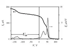
Fig. 2 illustrates the I-V characteristic and its first derivative of the Faraday cup with installed at output of the Inductively coupled plasma source powered with RF 13.56 MHz and operating at 6 mTorr of H2. The value of the electron-suppressor voltage (accelerating the ions) was set experimentally at , near the point of suppression of the secondary electron emission from the inner surface of the Faraday cup.[3]
Error sources
The counting of charges collected per unit time is impacted by two error sources: 1) the emission of low-energy secondary electrons from the surface struck by the incident charge and 2) backscattering (~180 degree scattering) of the incident particle, which causes it to leave the collecting surface, at least temporarily. Especially with electrons, it is fundamentally impossible to distinguish between a fresh new incident electron and one that has been backscattered or even a fast secondary electron.
See also
References
- ↑ Brown, K. L.; G. W. Tautfest (September 1956). "Faraday-Cup Monitors for High-Energy Electron Beams" (PDF). Review of Scientific Instruments. 27 (9): 696–702. Bibcode:1956RScI...27..696B. doi:10.1063/1.1715674. Retrieved 2007-09-13.
- ↑ Frank A. J. L. James (2004). "Faraday, Michael (1791–1867)". Oxford Dictionary of National Biography. Vol. 1 (online ed.). Oxford University Press. doi:10.1093/ref:odnb/9153. (Subscription or UK public library membership required.)
- ↑ E. V. Shun'ko. (2009). Langmuir Probe in Theory and Practice. Universal Publishers, Boca Raton, Fl. 2008. p. 249. ISBN 978-1-59942-935-9.