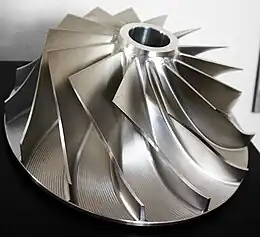
An impeller or impellor[1] is a driven rotor used to increase the pressure and flow of a fluid. It is the opposite of a turbine, which extracts energy from, and reduces the pressure of, a flowing fluid.
Strictly speaking, propellers are a sub-class of impellers where the flow both enters and leaves axially, but in many contexts the term "impeller" is reserved for non-propellor rotors where the flow enters axially and leaves radially, especially when creating suction in a pump or compressor.
In pumps


An impeller is a rotating component of a centrifugal pump that accelerates fluid outward from the center of rotation, thus transferring energy from the motor that drives the pump to the fluid being pumped.[2][3] The velocity achieved by the impeller transfers into pressure when the outward movement of the fluid is confined by the pump casing. An impeller is usually a short cylinder with an open inlet (called an eye) to accept incoming fluid, vanes to push the fluid radially, and a splined, keyed, or threaded bore to accept a drive shaft.
It can be cheaper to cast an impeller and its spindle as one piece, rather than separately. This combination is sometimes referred to simply as the "rotor."
Types
Open
An open impeller has a hub with attached vanes and is mounted on a shaft. The vanes do not have a wall, making open impellers slightly weaker than closed or semi-closed impellers. However, as the side plate is not fixed to the inlet side of the vane, the blade stresses are significantly lower.[4] In pumps, the fluid enters the impeller's eye, where vanes add energy and direct it to the nozzle discharge. A close clearance between vanes and pump volute or back plate prevent most of fluid from flowing back. Wear on the bowl and edge of vane can be compensated by adjusting the clearance to maintain efficiency over time.[5] Because the internal parts are visible, open impellers are easier to inspect for damage and maintain than closed impellers. They can also be more easily modified to change flow properties. Open impellers operate on a narrow range of specific speed. Open impellers are usually faster and easier to maintain. For small pumps and those dealing with suspended solids, open impellers are generally used.[6] Sand locking does not occur as easily as with closed type.
Semi-closed
A semi-closed impeller has an additional back wall, giving it more strength. These impellers can pass mixed solid-liquid mixtures at the cost of reduced efficiency.
Closed or shrouded
The construction of closed impellers includes additional back and front walls on both sides of vanes that enhances its strength. This also reduces the thrust load on the shaft, increasing bearing life and reliability and reducing shafting cost. However, this more complicated design, including the use of additional wear rings, makes closed impellers more difficult to manufacture and more expensive than open impellers. A closed impeller's efficiency decreases as wear ring clearance increases with use. However, adjustment of impeller bowl clearance does not affect the wear on vanes as critically as open impeller.[4] Closed impellers can be used on a wider range specific speed than open impellers.[5] They are generally used in large pumps and clear water applications. These impellers can't perform effectively with solids and become difficult to clean if clogged.[6]
Screw
The screw impeller design aligns more with an axial progressive channel that allows for solids to be openly handled when rotating.[7][8]
In centrifugal compressors
The main part of a centrifugal compressor is the impeller. An open impeller has no cover, therefore it can work at higher speeds. A compressor with a covered impeller can have more stages than one that has an open impeller.
In water jets
Some impellers are similar to small propellers but without the large blades. Among other uses, they are used in water jets to power high speed boats.
Because impellers do not have large blades to turn, they can spin at much higher speeds than propellers. The water forced through the impeller is channeled by the housing, creating a water jet that propels the vessel forward. The housing is normally tapered into a nozzle to increase the speed of the water, which also creates a Venturi effect in which low pressure behind the impeller pulls more water towards the blades, tending to increase the speed.
To work efficiently, there must be a close fit between the impeller and the housing. The housing is normally fitted with a replaceable wear ring which tends to wear as sand or other particles are thrown against the housing side by the impeller.
Vessels using impellers are normally steered by changing the direction of the water jet.
Compare to propeller and jet aircraft engines.
In agitated tanks

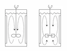
Impellers in agitated tanks are used to mix fluids or slurry in the tank. This can be used to combine materials in the form of solids, liquids and gas. Mixing the fluids in a tank is very important if there are gradients in conditions such as temperature or concentration.
There are two types of impellers, depending on the flow regime created (see figure):
- Axial flow impeller
- Radial flow impeller
Radial flow impellers impose essentially shear stress to the fluid, and are used, for example, to mix immiscible liquids or in general when there is a deformable interface to break. Another application of radial flow impellers is the mixing of very viscous fluids.
Axial flow impellers impose essentially bulk motion and are used on homogenization processes, in which increased fluid volumetric flow rate is important.
Impellers can be further classified principally into three sub-types:
Propellers
Propellers are axial thrust-giving elements. These elements give a very high degree of swirling in the vessel. The flow pattern generated in the fluid resembles a helix.
In washing machines

Some constructions of top loading washing machines use impellers to agitate the laundry during washing.
Firefighting rank badge
Fire services in the United Kingdom and many countries of the Commonwealth use a stylized depiction of an impeller as a rank badge. Officers wear one or more on their epaulettes or the collar of their firefighting uniform as an equivalent to the "pips" worn by the army and police.
In air pumps
Air pumps, such as the roots blower, use meshing impellers to move air through a system. Applications include blast furnaces, ventilation systems, and superchargers for internal combustion engines.
In medicine
Impellers are an integral part of axial-flow pumps, used in ventricular assist devices to augment or fully replace cardiac function.[9][10]
See also
References
- ↑ "impeller, n.". OED Online. March 2013. Oxford University Press. 20 March 2013 .
- ↑ Gülich, Johann Friedrich (2010). Centrifugal Pumps (2nd ed.). ISBN 978-3-642-12823-3.
- ↑ Manuals, Seloc Marine (2008). Volvo Penta Stern Drives 2003-2012: Gasoline Engines & Drive Systems (Seloc Marine Manuals. Seloc Publishing. ISBN 978-0893300746.
- 1 2 "Pump Design and Characteristic". The New Zealand Digital Library.
- 1 2 "Open vs. closed impellers – Mc Nally Institute". mcnallyinstitute.
- 1 2 "Open and Closed Impellers". Turbomachineary International.
- ↑ "Types of Impeller in Pumps - Selections and Considerations". 30 January 2021.
- ↑ Lin, Peng; Liu, Meiqing; Zhao, Wensheng; Liu, Zhiyong; Wu, Yuanwei; Xue, Fei; Zhang, Yipeng (2017). "Influence of tip clearance on the performance of a screw axial-flow pump". Advances in Mechanical Engineering. 9 (6). doi:10.1177/1687814017704357. S2CID 117627953.
- ↑ Miller, LW; Pagani, FD (2007). "Use of a continuous-flow device in patients awaiting heart transplantation". N Engl J Med. 357 (9): 885–96. doi:10.1056/nejmoa067758. PMID 17761592.
- ↑ Chou, N. K.; Wang, S. S.; Chu, S. H.; Chen, Y. S.; Lin, Y. H.; Chang, C. J.; Shyu, J. J.; Jan, G. J. (2001). "Physiologic analysis of cardiac cycle in an implantable impeller centrifugal left ventricular assist device". Artificial Organs. 25 (8): 613–6. doi:10.1046/j.1525-1594.2001.025008613.x. PMID 11531711.