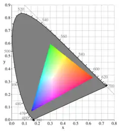
The grayed-out horseshoe shape is the entire range of possible chromaticities, displayed in the CIE 1931 chromaticity diagram format (see below). The colored triangle is the gamut available to the sRGB color space typically used in computer monitors; it does not cover the entire space. The corners of the triangle are the primary colors for this gamut; in the case of a CRT, they depend on the colors of the phosphors of the monitor. At each point, the brightest possible RGB color of that chromaticity is shown, resulting in the bright Mach band stripes corresponding to the edges of the RGB color cube.
In color reproduction, including computer graphics and photography, the gamut, or color gamut /ˈɡæmət/, is a certain complete subset of colors. The most common usage refers to the subset of colors that can be accurately represented in a given circumstance, such as within a given color space or by a certain output device.
Another sense, less frequently used but still correct, refers to the complete set of colors found within an image at a given time. In this context, digitizing a photograph, converting a digitized image to a different color space, or outputting it to a given medium using a certain output device generally alters its gamut, in the sense that some of the colors in the original are lost in the process.
Introduction
The term gamut was adopted from the field of music, where in middle age Latin "gamut" meant the entire range of musical notes of which musical melodies are composed; Shakespeare's use of the term in The Taming of the Shrew is sometimes attributed to the author / musician Thomas Morley.[1] In the 1850s, the term was applied to a range of colors or hue, for example by Thomas de Quincey, who wrote "Porphyry, I have heard, runs through as large a gamut of hues as marble."[2]
In color theory, the gamut of a device or process is that portion of the color space that can be represented, or reproduced. Generally, the color gamut is specified in the hue–saturation plane, as a system can usually produce colors over a wide intensity range within its color gamut; for a subtractive color system (such as used in printing), the range of intensity available in the system is for the most part meaningless without considering system-specific properties (such as the illumination of the ink).
When certain colors cannot be expressed within a particular color model, those colors are said to be out of gamut.
A device that can reproduce the entire visible color space is an unrealized goal within the engineering of color displays and printing processes. Modern techniques allow increasingly good approximations, but the complexity of these systems often makes them impractical.
While processing a digital image, the most convenient color model used is the RGB model. Printing the image requires transforming the image from the original RGB color model to the printer's CMYK color model. During this process, the colors from the RGB model which are out of gamut must be somehow converted to approximate values within the CMYK model. Simply trimming only the colors which are out of gamut to the closest colors in the destination space would burn the image. There are several algorithms approximating this transformation, but none of them can be truly perfect, since those colors are simply out of the target device's capabilities. This is why identifying the colors in an image that are out of gamut in the target color space as soon as possible during processing is critical for the quality of the final product. It is also important to remember that there are colors inside the CMYK gamut that are outside the most commonly used RGB color spaces, such as sRGB and Adobe RGB.
Representation of gamuts
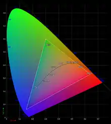 The CIE 1931 color space chromaticity diagram comparing the visible gamut with sRGB's and color temperature |
Gamuts are commonly represented as areas in the CIE 1931 chromaticity diagram, with the curved edge representing the monochromatic (single-wavelength) or spectral colors. |
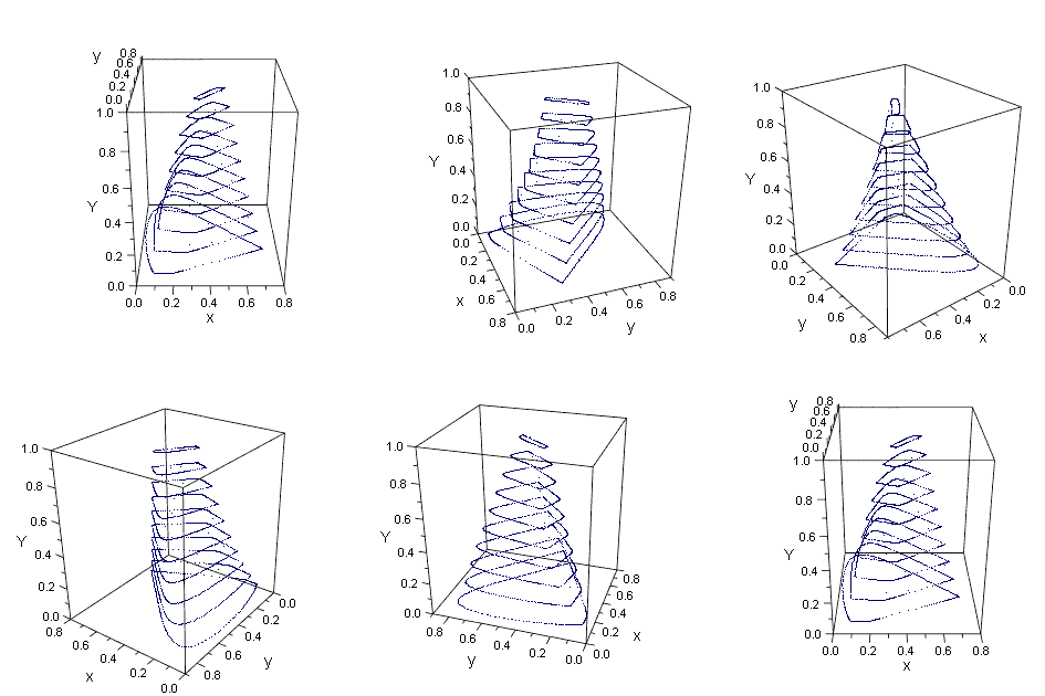
The sRGB gamut projected into the CIExyY color space. x and y are the horizontal axes and represent chromaticity. Y is the vertical axis and represent luminance. |
The accessible gamut depends on the brightness; a full gamut must therefore be represented in 3D space. |
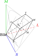 RGB gamut  Gamut of colors found in reflective surfaces in nature. |
The pictures show the gamuts of RGB color space (left), such as on computer monitors, and of reflective colors in nature (right). The cone drawn in grey corresponds roughly to the CIE chromaticity diagram, with the added dimension of brightness.
The axes in these diagrams are the responses of the short-wavelength (S), middle-wavelength (M), and long-wavelength (L) cones in the human eye. The other letters indicate black (Blk), red (R), green (G), blue (B), cyan (C), magenta (M), yellow (Y), and white colors (W). (Note: These pictures are not exactly to scale.) The right diagram shows that the shape of the RGB gamut is a triangle between red, green, and blue at lower luminosities; a triangle between cyan, magenta, and yellow at higher luminosities, and a single white point at maximum luminosity. The exact positions of the apexes depends on the emission spectra of the phosphors in the computer monitor, and on the ratio between the maximum luminosities of the three phosphors (i.e., the color balance). The gamut of the CMYK color space is, ideally, approximately the same as that for RGB, with slightly different apexes, depending on both the exact properties of the dyes and the light source. In practice, due to the way raster-printed colors interact with each other and the paper and due to their non-ideal absorption spectra, the gamut is smaller and has rounded corners. |
The gamut of reflective colors in nature has a similar, though more rounded, shape. An object that reflects only a narrow band of wavelengths will have a color close to the edge of the CIE diagram, but it will have a very low luminosity at the same time. At higher luminosities, the accessible area in the CIE diagram becomes smaller and smaller, up to a single point of white, where all wavelengths are reflected exactly 100 percent; the exact coordinates of white are determined by the color of the light source.
Limitations of color representation
Surfaces
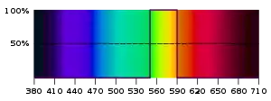
In the beginning of the 20th century, industrial demands for a controllable way to describe colors and the new possibility to measure light spectra initiated intense research on mathematical descriptions of colors.
The idea of optimal colors was introduced by the Baltic German chemist Wilhelm Ostwald. Erwin Schrödinger showed in his 1919 article Theorie der Pigmente von größter Leuchtkraft (Theory of Pigments with Highest Luminosity)[3] that the most-saturated colors that can be created with a given total reflectivity are generated by surfaces having either zero or full reflectance at any given wavelength, and the reflectivity spectrum must have at most two transitions between zero and full.
Thus two types of "optimal color" spectra are possible: Either the transition goes from zero at both ends of the spectrum to one in the middle, as shown in the image at right, or it goes from one at the ends to zero in the middle. The first type produces colors that are similar to the spectral colors and follow roughly the horseshoe-shaped portion of the CIE xy chromaticity diagram, but are generally less saturated. The second type produces colors that are similar to (but generally less saturated than) the colors on the straight line in the CIE xy chromaticity diagram, leading to magenta-like colors.
Schrödinger's work was further developed by David MacAdam and Siegfried Rösch.[4] MacAdam was the first person to calculate precise coordinates of selected points on the boundary of the optimal color solid in the CIE 1931 color space for lightness levels from Y = 10 to 95 in steps of 10 units. This enabled him to draw the optimal color solid at an acceptable degree of precision. Because of his achievement, the boundary of the optimal color solid is called the MacAdam limit (1935).
In 1980, Michael R. Pointer published a maximum gamut for real surfaces with diffuse reflection using 4089 samples, (surfaces with specular reflection ("glossy") can fall outside of this gamut).[5] Originally called a "Munsell Color Cascade", the limits are more commonly called Pointer's Gamut after his work. This gamut remains important as a reference for color reproduction,[6] having been updated by newer methods in ISO 12640-3 Annex B.[7]
On modern computers, it is possible to calculate an optimal color solid with great precision in seconds. The MacAdam limit, on which the most saturated (or "optimal") colors reside, shows that colors that are near monochromatic colors can only be achieved at very low luminance levels, except for yellows, because a mixture of the wavelengths from the long straight-line portion of the spectral locus between green and red will combine to make a color very close to a monochromatic yellow.
Light sources
Light sources used as primaries in an additive color reproduction system need to be bright, so they are generally not close to monochromatic. That is, the color gamut of most variable-color light sources can be understood as a result of difficulties producing pure monochromatic (single wavelength) light. The best technological source of monochromatic light is the laser, which can be rather expensive and impractical for many systems. However, as optoelectronic technology matures, single-longitudinal-mode diode lasers are becoming less expensive, and many applications can already profit from this; such as Raman spectroscopy, holography, biomedical research, fluorescence, reprographics, interferometry, semiconductor inspection, remote detection, optical data storage, image recording, spectral analysis, printing, point-to-point free-space communications, and fiber optic communications.[8][9][10][11]
Systems that use additive color processes usually have a color gamut which is roughly a convex polygon in the hue-saturation plane. The vertices of the polygon are the most saturated colors the system can produce. In subtractive color systems, the color gamut is more often an irregular region.
Comparison of various systems

Following is a list of representative color systems more-or-less ordered from large to small color gamut:
- A laser video projector uses three lasers to produce the broadest gamut available in practical display equipment today, derived from the fact that lasers produce truly monochromatic primaries. The systems work either by scanning the entire picture a dot at a time and modulating the laser directly at high frequency, much like the electron beams in a CRT, or by optically spreading and then modulating the laser and scanning a line at a time, the line itself being modulated in much the same way as in a DLP projector. Lasers can also be used as a light source for a DLP projector. More than three lasers can be combined to increase the gamut range, a technique sometimes used in holography.[12]
- Digital Light Processing or DLP technology is a trademarked technology from Texas Instruments. The DLP chip contains a rectangular array of up to 2 million hinge-mounted microscopic mirrors. Each of the micromirrors measures less than one-fifth the width of a human hair. A DLP chip's micromirror tilts either toward the light source in a DLP projection system (ON) or away from it (OFF). This creates a light or dark pixel on the projection surface.[13] Current DLP projectors use a quickly rotating wheel with transparent colored "pie slices" to present each color frame successively. One rotation shows the complete image.
- Photographic film can reproduce a larger color gamut than typical television, computer, or home video systems.[14]
- CRT and similar video displays have a roughly triangular color gamut which covers a significant portion of the visible color space. In CRTs, the limitations are due to the phosphors in the screen which produce red, green, and blue light.
- Liquid crystal display (LCD) screens filter the light emitted by a backlight. The gamut of an LCD screen is therefore limited to the emitted spectrum of the backlight. Typical LCD screens use cold-cathode fluorescent bulbs (CCFLs) for backlights. LCD Screens with certain LED or wide-gamut CCFL backlights yield a more comprehensive gamut than CRTs. However, some LCD technologies vary the color presented by viewing angle. In Plane Switching or Patterned vertical alignment screens have a wider span of colors than Twisted Nematic.
- Television normally uses a CRT, LCD, LED or plasma display, but does not take full advantage of its color display properties, due to the limitations of broadcasting. The common color profile for TV is based on ITU standard Rec. 601. HDTV is less restrictive and uses a slightly improved color profile based on ITU standard Rec. 709. Still somewhat less than, for example, computer displays using the same display technology. This is due to the use of a limited subset of RGB in broadcasting (values from 16-235), versus full RGB in computer displays, where all bits from 0 to 255 are used.
- Paint mixing, both artistic and for commercial applications, achieves a reasonably large color gamut by starting with a larger palette than the red, green, and blue of CRTs or cyan, magenta, and yellow of printing. Paint may reproduce some highly saturated colors that cannot be reproduced well by CRTs (particularly violet), but overall the color gamut is smaller.
- Printing typically uses the CMYK color space (cyan, magenta, yellow, and black). Very few printing processes do not include black; however, those processes (with the exception of dye-sublimation printers) are poor at representing low saturation, low intensity colors. Efforts have been made to expand the gamut of the printing process by adding inks of non-primary colors; these are typically orange and green (see Hexachrome) or light cyan and light magenta (see CcMmYK color model). Spot color inks of a very specific color are also sometimes used.
- A monochrome display's color gamut is a one-dimensional curve in color space.[15]
Wide color gamut
The Ultra HD Forum defines a wide color gamut (WCG) as a color gamut wider than that of BT.709 (Rec. 709).[16] Color spaces with WCGs include:
- Rec. 2020 – ITU-R Recommendation for UHDTV[17]
- Rec. 2100 – ITU-R Recommendation for HDR-TV (same chromaticity of color primaries and white point as Rec. 2020)[18]
- DCI-P3
- Adobe RGB color space
Extended-gamut printing
The print gamut achieved by using cyan, magenta, yellow, and black inks is sometimes a limitation, for example when printing colors of corporate logos. Therefore, some methods of color printing use additional ink colors to achieve a larger gamut. For example, some use green, orange, and violet inks to increase the achievable saturation of hues near those. These method are variously called heptatone color printing, extended gamut printing, and 7-color printing, etc.[19][20]
References
- ↑ Long, John H. (1950). "Shakespeare and Thomas Morley". Modern Language Notes. 65 (1): 17–22. doi:10.2307/2909321. JSTOR 2909321.
- ↑ de Quincey, Thomas (1854). De Quincey's works. James R. Osgood. p. 36.
gamut-of-hues 0-1856.
- ↑ Schrödinger, Erwin (1919). "Theorie der Pigmente größter Leuchtkraft". Annalen der Physik. 367 (15): 603–622. Bibcode:1920AnP...367..603S. doi:10.1002/andp.19203671504.
- ↑ Lee, Hsien-Che (2005). "18.7: Theoretical color gamut". Introduction to Color Imaging Science. Cambridge University Press. p. 468. ISBN 1-139-44455-7. Retrieved 22 September 2022.
- ↑ Charles Poynton (2010). "Wide-gamut image capture". Society for Imaging Science and Technology. p. 472.
- ↑ Tatsuhiko Matsumoto; Yoshihide Shimpuku; Takehiro Nakatsue; Shuichi Haga; Hiroaki Eto; Yoshiyuki Akiyama & Naoya Katoh (2006). 19.2: xvYCC: A New Standard for Video Systems using Extended-Gamut YCC Color Space. SID INTERNATIONAL SYMPOSIUM. Society for Information Display. pp. 1130–1133. doi:10.1889/1.2433175.
- ↑ Holm, J; Tasti, I; Johnson, T. "Definition & Use of the ISO 12640-3 reference color gamut". pp. 62–8.
- ↑ "Single Frequency Laser – Single Longitudinal Mode Laser". Retrieved 26 February 2013.
- ↑ "JDSU – Diode Laser, 810 or 830 or 852 nm, 50-200 mW, Single-Mode (54xx Series)". Archived from the original on 25 March 2014. Retrieved 26 February 2013.
- ↑ "Laserglow Technologies – Handheld Lasers, Alignment Lasers and Lab / OEM Lasers". Archived from the original on 23 January 2013. Retrieved 26 February 2013.
- ↑ "Laser Diode Characteristics". Retrieved 26 February 2013.
- ↑ Bjelkhagen, Hans I.; Mirlis, Evangelos (2008). "Color holography to produce highly realistic three-dimensional images". Applied Optics. 47 (4): A123-33. doi:10.1364/AO.47.00A123. PMID 18239694.
- ↑ "DLP Technology". Retrieved 14 February 2010.
- ↑ "Film gamut, apples, and oranges". Archived from the original on 17 September 2008. Retrieved 26 April 2007.
- ↑ Velho, Luiz; Frery, Alejandro C.; Gomes, Jonas (29 April 2009). Image Processing for Computer Graphics and Vision. Springer Science & Business Media. ISBN 978-1-84800-193-0.
- ↑ Ultra HD Forum (19 October 2020). "Ultra HD Forum Guidelines v2.4" (PDF). Archived (PDF) from the original on 20 November 2021. Retrieved 11 February 2021.
- ↑ "BT.2020 : Parameter values for ultra-high definition television systems for production and international programme exchange". www.itu.int. Retrieved 11 February 2021.
- ↑ "BT.2100 : Image parameter values for high dynamic range television for use in production and international programme exchange". www.itu.int. Retrieved 11 February 2021.
- ↑ Ostromoukhov, Victor (1993). "Chromaticity gamut enhancement by heptatone multi-color printing". Device-independent Color Imaging and Imaging Systems Integration. Vol. 1909. SPIE. pp. 139–151). ISBN 0-8194-1142-6. Retrieved 23 June 2021.
- ↑ "Print brand colors accurately with a fixed set of inks".
External links
- Using the Chromaticity Diagram for Color Gamut Evaluation by Bruce Lindbloom.
- Color Gamut Mapping book by Jan Morovic.
- Quantifying Color Gamut by William D. Kappele
- Stanford University CS 178 interactive Flash demo explaining color gamut mapping.
- Wide Color Gamut by Ujjwal Bhardwaj.
