| type | home |
| manufacturer | Singer Manufacturing Company |
| material | fabric |
| stitch | lockstitch |
| power | treadle, handcrank, add-on electric |
| feed | drop |
| needle(s) | one 15x1 (except VS1, which uses 20x1)[1] |
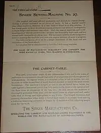
The Singer Model 27 and later model 127 were a series of lockstitch sewing machines produced by the Singer Manufacturing Company from the 1880s to the 1960s. (The 27 and the 127 were full-size versions of the Singer 28 and later model 128 which were three-quarters size). They were Singer's first sewing machines to make use of "vibrating shuttle" technology. Millions were produced.[lower-alpha 1] They are all steel and cast iron, and were built before the advent of planned obsolescence, and so they were designed to be repaired rather than replaced.[lower-alpha 2] Consequently many remain today, some in collections and others still in service. In company literature they were called "the woman's faithful friend the world over".[2]
Identifying characteristics
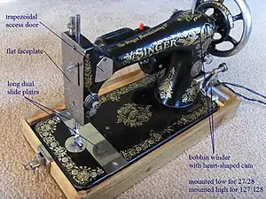
The many Vintage Singer sewing machine models look very similar. All machines in the 27 series (VS-1, VS-2, VS-3, 27, 28, 127, and 128) have the following distinguishing characteristics that can be used to differentiate them from other Singer machines:
- Split slide plates running the entire depth of bed
- Flat face plate, most are ornamented with grapevines but very early examples have a plain shiny finish.
Within the 27 series are seen the following differences between versions:[3]
| Characteristic | VS-1 | VS-2 | 27 | VS-3 | 28 | 127 | 128 |
|---|---|---|---|---|---|---|---|
| Trapezoidal access door on head | no | yes | yes | yes | yes | yes | yes |
| Location of stitch length control | bed | pillar | pillar | pillar | pillar | pillar | pillar |
| Bed shape | fiddle | fiddle | rectangle | rectangle | rectangle | rectangle | rectangle |
| Bed width (inches) | 14-5/8 | 14-5/8 | 14-5/8 | 12-5/32 | 12-5/32 | 14-5/8 | 12-5/32 |
| Bed depth (inches) | 7 | 7 | 7 | 6-9/16 | 6-9/16 | 7 | 6-9/16 |
| Space between needle and pillar | 8 | 8 | 8 | 6-1/2 | 6-1/2 | 8 | 6-1/2 |
| Bobbin winder location | low | low | low* | low | low* | high | high |
| Shuttle ejector button | no | no | no | no | no | yes | yes |
| * A few older machines have moved their bobbin winders to the high position, but they will still have a mounting lug for it in the original lower position. | |||||||
Vibrating shuttle
The 27 series was Singer's first[lower-alpha 3] use of a vibrating shuttle as a bobbin driver, instead of the transverse shuttle design used in the older 'New Family' machine.
History
The design of the model 27 series began with Allen B. Wilson, who invented the vibrating shuttle in 1850 and sold machines built around it. Two decades later, when the patents had expired and the Sewing Machine Combination patent pool had dispersed, White Sewing Machine Company employees D'Arcy Porter and George W. Baker built a new machine that made successful use of it. The "White Sewing Machine", as it was first named, entered production in 1876. It was popular in its time, and some of them remain.[lower-alpha 4]
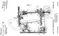
In the decade that followed, another gentleman applied his mind to advancing the state of the art. Scottish immigrant Robert Whitehill (1 June 1845[4] – 24 November 1903[5]), founder of the Whitehill Manufacturing Company, became interested in sewing machines and subsequently patented an improvement to the take-up arm.[6] He proceeded to manufacture his own machines from about 1875[7] until 1883. He then designed the sewing machine which would shortly become Singer's answer to the White machine. He applied for patent on 1 July 1884 and received US patent 326821 on 22 September 1885.
In his design Whitehill retained the White machine's dimensions and most aspects of its exterior; his contribution mainly consists of the new interior. That is, he rethought the entire powertrain—the mechanism that carries energy from the handwheel to the needlebar, to the bobbin driver, and to the feed dogs. He also conceived the bullet-shaped shuttle, which the White machine promptly adopted over its more traditional boat shuttle.[8]
He took his prototype to the Singer head office and showed it to the office manager James Bolton (1832–1916). Bolton was thrilled with the machine and suggested a sewing competition against the best Singer models on-hand at the factory. Whitehill's prototype prevailed, and he sold the rights to it for USD 8,000 (USD 212,000 adjusted), with USD 1,000 held in reserve until he had perfected it for them.[9]
At the time, Singer was already selling two "high arm" models (one a chain stitcher, the other an oscillating shuttle) which represented a new break from the company's established history of "low arm" machines. The Whitehill design became the third Singer machine with a high arm, and quickly eclipsed the other two—neither of which Bolton liked anyway.[10] The Whitehill machine took the name "Vibrating Shuttle 1" when, two years later, it evolved into the improved "Vibrating Shuttle 2".
Within a couple of years Scientific American took notice, and printed the following praise for Whitehill's design, especially for its powertrain:[11]
Of Vibrating Shuttles
These are shuttles of the long description, moving in a segment of a circle. There are several varieties. The most novel machine of this kind is the vibrating shuttle machine just produced by the Singer Manufacturing Company. In this case the shuttle itself consists of a steel tube, into the open end of which the wound reel is dropped, and is free to revolve quite loosely. Variation of tension is thus obviated in a very simple manner. The chief point of interest in the machine is undoubtedly the means employed in transferring the motion from the main shaft to the underneath parts, an arrangement as ingenious and effective as any device ever introduced into stitching mechanism. It is the invention of Mr. Robert Whitehall [sic], and consists of a vertical rocking shaft situated in the arm of the machine[.] Motion is imparted to it by means of an elbow formed upon the main shaft acting upon two arms, called wipers, projecting from the rocking shaft, the angle formed by the arms exactly coinciding with that of the elbow in its revolution.
This admirable motion will no doubt attract much attention from mechanists and engineers.
Production
The 27 series had a long production run, including improved versions and many variants tailored to customer needs.
Versions
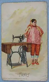
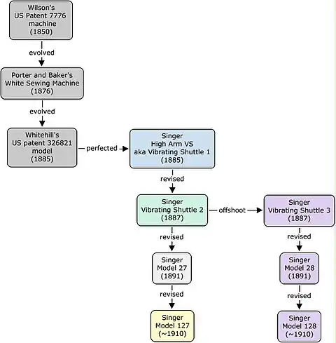
The model series evolved over time through these versions:
| Year | Original name | Currently AKA | Notes |
|---|---|---|---|
| 1885-1887 | High Arm (VS version), Vibrating Shuttle 1, V.S. No. 1 | experimental, very low production | |
| 1887-1891 | Vibrating Shuttle 2, V.S. No. 2 | Model 27-2*, Model 27 Fiddlebed | shuttle overhauled |
| 1891-1913 | Model 27 | bed changed to rectangular | |
| ~1910-1940s** | Model 127 | a 'modernized' 27—see 'Modernization' below | |
| * Not to be confused with the 27-2 variant; see Variations table below.
** Many records from this era were lost during World War II. | |||
Portable versions
A model 27/127 coincidentally weighs 27 pounds (12 kg), plus the weight of its motor; treadle or hand crank; light; and case or cabinet. Such a weight strains the meaning of the term "portable", even when fitted with only a hand crank and minimal wood case. By comparison, today's laptop computers typically weigh 3 to 5 pounds (1.4 to 2.3 kg).) The weight of the 27/127 led Singer to produce a 3/4 size version intended for portability, just as the White Sewing Machine Company was doing with its new 3/4 size "Peerless" machine.
Singer's portable version evolved thus:
| Year | Original name | Currently AKA | Notes |
|---|---|---|---|
| ~1886-~1890 | Vibrating Shuttle 3, V.S. No. 3 | Model 28-1 | evolved from the VS-2; bed changed to rectangular |
| ~1890-1918 | Model 28 | Model 28-2 | |
| ~1910-1962 | Model 128 | a 'modernized' 28—see 'Modernization' below |
Modernization
Models 127 and 128 are the "modernized" versions of the 27 and 28, and carry the following improvements:
- A new shuttle ejector button, invented in 1910,[12] eases removal of the shuttle for rethreading. The button is located on the improved shuttle frame, Singer part number 54507, which can be retrofitted onto older model 27 and 28 machines.
- The bobbin winder is mounted high on the pedestal, where a small rubber tire occupying its pulley makes contact with the motor belt. The new mounting position solves the bobbin winder belt problem discussed later.
- Dedicated motor mounting lugs, cast into the rear of the pillar, standardize the position of the motor bracket. A decade later, motor designs will settle down into a side-mounted motor that attaches to these lugs using an L-shaped bracket.
- Automatic tension release when the presser bar is lifted, replacing the manual tension release achieved by pressing a spoon shaped device just below the tension regulator in the earlier machines. This device is no longer present in the 127 and 128.
- The shuttle was modified again—see below.
Shuttle changes
With each major new version came changes in the shuttle:[13]
| Models | Shuttle assembly part number | Shuttle body part number | Notes | Picture |
|---|---|---|---|---|
| VS-1 | ? | ? | originally like the White Sewing Machine's shuttle, but there were many changes as the VS-1 evolved |  |
| VS-2, VS-3 | 8227 | unknown* | hemicircular pit added to shuttle nose |  |
| 27, 28 | 8327 | 8301* | wasp waist added |  |
| 127, 128 | 54505 | 54504 | oval pit added to shuttle face,
hemicircular pit removed from shuttle nose, shuttle face larger |
 |
| * Singer parts lists give contradictory information about the 8301 shuttle body. The parts lists state[14] that both the 8227 and the 8327 shuttle assemblies use it, but the pictures given of those assemblies show completely different shuttle bodies. The correct answer is probably 8327 because shuttles found in the wild stamped "8301" or sometimes "301" are the later wasp-waisted sort. | ||||
None of the four shuttle models can be substituted for each other; if they even fit at all, they will cause skipped stitches. However, there was once an aftermarket of replacement shuttles, and the replacements were sometimes contrived to be compatible with both the 27/28 and 127/128 models. Consequently there are extant shuttles which have no stamped part number and which bear the features of both the 8301 and 54504.
Variations
Once production settled down into the model 27 and 28 versions, Singer produced many variants that were intended for different cabinets and power sources. The variant number was listed after the version number and (except for the K designation) a dash; for example, the model 27 standard treadle variant is "27-3".
| Variant | Difference[15] |
|---|---|
| 27-1, 28-1, 127-1, 128-1 | standard treadle variant, designation later changed to 3 to avoid confusion with V. S. No. 1 version* |
| 27-2, 28-2, 127-2, 128-2 | standard hand-crank variant, designation later changed to 4 to avoid confusion with V. S. No. 2 version* |
| 27-3, 28-3, 127-3, 128-3 | standard treadle variant, designation usually omitted** |
| 27-4, 28-4, 127-4, 128-4 | standard hand-crank variant |
| 28-8[16] | treadle, export only |
| 28-9[14] | hand-crank, export only |
| 127-12 | treadle, no take-up lever cover |
| 127-13 | pre-fitted with 'BT' or 'BR' add-on motor and Singerlight |
| 127-14 | hand-crank, no take-up lever cover |
| 127-23 | pre-fitted with 'BY17' or 'BZ17' add-on motor and spotlight, intended for mounting in a cabinet |
| 127-24 | pre-fitted with 'BY18' or 'BZ18' add-on motor and spotlight, intended for mounting in a portable case |
| 128-8 | pre-fitted with 'BS' add-on motor and spotlight, solid handwheel |
| 128-12 | treadle, no thread cutter, no shuttle ejector, no take-up lever cover |
| 128-13 | pre-fitted with 'BT' add-on motor and Singerlight |
| 128-14 | hand-crank, no thread cutter, no shuttle ejector, no take-up lever cover |
| 128-18 | pre-fitted with 'BY17' or 'BZ17' add-on motor and spotlight, no thread cutter, no shuttle ejector, no take-up lever cover, solid handwheel |
| 128-23 | pre-fitted with 'BY8', 'BY9', 'BZ8', or 'BZ9' add-on motor and spotlight, solid handwheel, intended for mounting in a portable case |
| K | built at Singer's 'Kilbowie' factory in Clydebank, Scotland |
| * Today the ambiguous designations "27-1", "27-2", and "28-1" almost always refer to the early versions rather than to the later variants.
** Singer serial number archives for the models 27 and 28 often omit the -3 designation but mention the -4 designation, and vice versa. | |
Production records
Many records from the era of the 27/127 are missing, so the production timeline is spotty. The following is the best information available from the Singer archives.[17]
| Machine | First surviving record | Last surviving record | Notes |
|---|---|---|---|
| Vibrating Shuttle 1 | (none) | (none) | |
| Vibrating Shuttle 2 | (none) | (none) | |
| Vibrating Shuttle 3 | (none) | (none) | |
| Model 27 | (none) | St. Jean factory batch G2584401-G2609400, allocated 6 January 1913 | |
| Model 28 | (none) | Elizabethport factory batch G6463896-G6488895, allocated 9 October 1918 | |
| Model 127 | Kilbowie factory batch F3018545-F3093544, allocated July 1912 | Elizabethport factory batch AF948851-AF953850, allocated 28 May 1941 | Many records lost during World War II. |
| Model 128 | Kilbowie factory batch F2612805-F2613304, allocated January 1912 | Kilbowie factory batch ET613325-ET638324, allocated 17 July 1962 |
Competitors
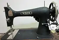
At about USD100 apiece (about USD2500 adjusted), Singer sewing machines were pricey, even considering the payment plans and trade-in allowances that were offered. The high prices created a demand for similar machines made by competitors. The main sales outlets were Sears Roebuck & Co and Montgomery Wards & Co, who sold badged models made by a variety of manufacturers:[18]
| Manufacturer | Singer model | Knock-off name |
|---|---|---|
| Goodrich Machine Sewing Company | VS-1? | Minnesota |
| The Free Sewing Machine Company | VS-2 | ACME |
| The Davis Sewing Machine Company | VS-2 | Minnesota-B, Burdick |
| Illinois Sewing Machine Company | 27 | New Royal[19] |
| White Sewing Machine Company | 27 | Franklin, "Long Shuttle" |
| White Sewing Machine Company | 127 | Number 8 |
| Domestic Sewing Machine Company | 27 | Franklin |
| Domestic Sewing Machine Company | 127 | Minnesota-A, Minnesota New Model A, Minnesota-H |
| Standard Sewing Machine Company | VS-2? | Minnesota-L |
Power
The 27 model series had three options for power: foot treadle, hand crank, and external electric motor.
Treadle
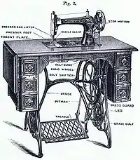
A treadle obtains power from the user's legs. Early treadles were for just one foot making a heel-toe rocking motion, but all later treadles, including those offered with 27-series machines, were for two feet making a left-heel-right-toe (or vice versa) motion. The treadle provided with 27-series machines has a negative mechanical advantage: one complete down-up motion produces exactly four stitches.[20]
As a foot treadle, the machine mounts in a cabinet about the size of an adult schooldesk. The treadle pad is built into the cabinet's base right at the user's feet. A round leather "treadle belt" passes up from the treadle, up through the cabinet, over the handwheel by following the belt groove, back down through the cabinet again, and then back to the treadle.
The belt is joined end-to-end with a clip to make a loop, and can be shortened and reclipped (using special "treadle belt pliers") as needed to keep proper tension. The treadle belt is tanned leather, 3/16" in diameter, and is normally sold in 72" lengths.
Hand crank
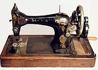
Hand cranks provide greater portability at the cost of greater exertion. A hand crank machine fit in a small case, making it a piece of luggage rather than a piece of furniture. It also cost significantly less than a full treadle. Indeed, the 3/4th size model 28/128 derivative was specifically intended for this end.
The crank is geared to give a negative mechanical advantage so that it can crank the machine at high speed. Each rotation of the crank handle produces three rotations of the handwheel, and hence three stitches.
External electric motor
Electric motors were offered (by Singer and others) to retrofit these and other treadle machines with electric power.
Cabinet-mount
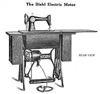
Early electric conversions consisted of mounting a motor in the treadle cabinet. The treadle belt was shortened to run only from the motor's pulley to the handwheel. The treadle pad was then given a mechanism for controlling the motor's speed in the manner of a modern car gas pedal.[20]
These conversions were invented and developed by Philip Diehl, an inventor under contract with Singer.[21] His efforts bore fruit in 1884,[14] before the first VS-1 was even built and fully five years before Singer's first natively electrified model.[22] He continued to make improvements for many years thereafter.[23]
Pillar-mount

Later motor kits dispensed entirely with the treadle, treadle belt, and cabinet. The motor bolted right to the machine's pillar, where—thanks to its compact size—it could remain even when the machine was tilted into its cabinet or enclosed within its cover. This was an improvement over earlier pivoting-motor designs,[24] large offset belt-drive motors,[25] and the many schemes for entirely replacing the handwheel with a motor.[26] Credit for the original idea may belong to George F. Green, who proposed it back in 1879[27] but was probably unable to build or obtain the sufficiently compact motor required by his design. It was Frederick Diehl and Martin Hemler, Singer employees, who finally developed the idea in 1921.[28]
Speed is controlled by a rheostat, originally mounted on the treadle pad[29] but later as an independent pedal for foot or knee control. The kit includes a dual electrical outlet that mounts alongside the machine in its case: one outlet is for the motor and is controlled by the foot pedal; the other is for a sewing lamp (see below) and is always energized. A sewing machine thus electrified now fit entirely inside a woman-portable carrying case.
Electric motors became so common that Singer made provision for them: the model 127/128 'modernized' versions included mounting lugs for a motor, whereas earlier models had to be drilled and tapped. Some 127/128 machines[30] were even given motors right at the factory, and of those, a few models[31] used a smaller lighter solid handwheel instead of the larger heavier spoked handwheel used on machines sold as treadles. The spoked handwheel is better for treadles because its larger inertia keeps it spinning longer, whereas the lighter solid handwheel is better for motors because its smaller inertia causes it to start and stop more quickly.
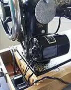 Add-on motor kit showing pedal-controlled electrical outlet
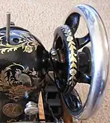 Older spoked handwheel
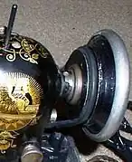 Newer solid handwheel
A few older 27 and 28 machines have also shown up with solid handwheels, which they must have received retrofit during the addition of their electric motor.
Belts
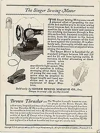
The add-on motor drives the handwheel by means of a rubber belt. Meanwhile the bobbin winder has a separate belt: the models 27 and 28 drive the bobbin winder using a long round or V belt to the motor, whereas the 'modernized' models 127 and 128 drive the bobbin winder directly off the handwheel by means of a small "ring belt" or "bobbin belt" acting as a tire.
| Model | Belt | Belt race
inner length |
Belt race
outer length |
Adjustment
range +/- |
V belt | Stretch belt |
|---|---|---|---|---|---|---|
| 27*, 28*, 127, 128
spoked handwheel |
motor belt | 14-3/4 inches | 15-3/4 inches | 1/4 inch | Singer 193077
(15-3/8 inches) |
Singer 2125
or Dritz 903 (13-1/2 inches) or similar |
| 27*, 28*, 127, 128
solid handwheel |
motor belt | ? | ? | 1/4 inch | Singer 193066
(14-1/4 inches) |
Singer 2125
or Dritz 903 (13-1/2 inches) or similar |
| 27, 28 | bobbin winder belt | 10-3/4 inches | 11-7/8 inches | 1/2 inch | see below | see below |
| 127, 128 | bobbin winder tire | 5/8 inch | 1-1/8 inch | 0 | not applicable | Singer 15287A
(included in Singer 2125 and Dritz 903) |
| * Models 27 and 28 do not have a motor mount hardpoint; the hardpoint appeared later on the models 127 and 128. Without a hardpoint, screw holes must be manually drilled and tapped into the pillar for the motor mounting bolts. Unfortunately there is not a standard location for these screw holes, and so the add-on motor can be mounted anywhere within a two-inch range on the pillar. Consequently, the belt race length can vary from the standard race lengths of the 127 and 128. If it does vary, then the standard Singer V belts can be too long or too short. In that case a stretch belt (good over a range of several inches) will suffice instead. | ||||||
Difficulties with 27/28 bobbin winder belt
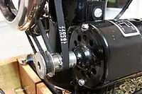
Models 27 and 28 were designed before electrified sewing machines were common, and the location of the bobbin winder reflects this. It is positioned to intercept the treadle belt as it passes back down into the cabinet. Motorization removes the treadle belt and so opens the question of how to drive the bobbin winder.
To answer this, the modernized models 127 and 128 moved the bobbin winder up several inches where, with a suitable tire, it can run directly off the handwheel. The older 27 and 28, on the other hand, require a dedicated belt to drive the bobbin winder, but the motor kit only has one pulley, resulting in problems:
- Driving both the handwheel and the bobbin winder with a single belt running in a triangular path causes traction problems at the motor, due to decreased belt contact area (from 90 degrees to about 60 degrees). This can be compensated by high belt tension, but that in turn will wear out the bearings and quickly exhaust a stretch belt.
- Driving the bobbin winder with a separate belt, hooked onto the motor pulley whenever needed, means that the standard V belt cannot be used to drive the handwheel. A less-desirable stretch belt, easier to get onto and off the motor pulley, must be used instead.
One solution to the problem has been spotted in a wild: tack-weld a second pulley onto the motor pulley, as shown in the picture.
Sewing lamp
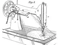
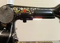
Motor kits usually included a sewing lamp. Singer's motor kits and factory motorizations each included one of two different sorts of lamp:
- Spotlights cast their light in just one direction and are known to run hot. They attach at any screw-hole on the machine, using a short metal arm with thumbscrew.
- 'Singerlights' have an elongated bulb and shade which casts its light over most of the bed. They attach to the machine's pillar access port underneath the round cover, sharing its thumbscrew. The Singerlight compatible with 27-series machines is Singer part number B428. It was originally invented by Frederick Diehl in 1921,[32] and a coworker soon followed with additional patented improvements.[33]
As there were many clones of the add-on motor, so also were there many clones of the Singerlight. Mercury Electric Products Manufacturing Company, aka MEPM, was one of the third-party vendors of such products.
Finish and decals
Most machines in this model series are painted in Japan black lacquer, but some of the later variants (127-12, 127-14, 127-23, 128-8, 128-12, 128-14, and 128-18) were instead finished in the newly fashionable, low-glare "black wrinkle" (aka "Godzilla" or "black crinkle") finish. They were all then 'ornamented' with extensive eye-catching decals. Common decal sets have names and are shown below; alternatively, many machines carry nondescript floral patterns.
 La Vincendora (28/128 only)
 Ottoman Carnation
 Peacock tail
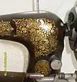 Persian
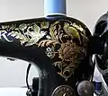 Pheasant
 Rococo (28/128 only)
 Rose and Cornflower (aka Painted Roses)
 Sphinx (aka Memphis, Egyptian)
 Tiffany (aka Gingerbread)
 Victorian
Accessories
27-series machines have a standard "low shank" and so are compatible with all ordinary low-shank attachments.
Singer also produced many attachments specifically for their own machines "which will enable you to accomplish a great variety of work with a minimum of time and effort... attachments which can give your home sewing that smart professional look."[34]
'Style' boxes
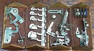
Singer accessory kits were sold in fold-out 'Style' boxes, numbered consecutively as newer versions evolved from older ones. The numbers begin at 1 ("Style No. 1") and culminate at 14 during the era of the 27 model series. The boxes included accessory attachments for hemming, braiding, underbraiding, tucking, shirring, binding, quilting, and ruffling, plus spare needles, bobbins, screws, and screwdrivers.
Today such a box is called a "puzzle box", but this is a recent term: it is not mentioned in the original Style manuals.
Hemstitcher
Singer separately sold a hemstitching attachment that is compatible with 27-series machines. The original version is a passive device, Singer part number 28915.[35] Later, a more sophisticated needle-clamp-powered attachment was offered—Singer part number 121387.
Buttonholer
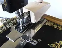
Because 27-series machines cannot natively sew a zigzag stitch, they cannot feasibly sew a buttonhole. To rectify this, Singer produced an evolving line of buttonholer attachments that mount on the machine's shank and provide the missing functionality.
Zigzagger
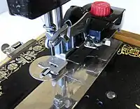
Singer made an attachment similar to its buttonholer, and using a similar needle-clamp-powered locomotion, in order to confer some zigzagging ability on its straight-stitch machines.
Of the variety of "Singer Automatic Zigzagger" attachments produced over the years, two are compatible with 27-series machines: Singer part numbers 160985 and 161102.
Blind stitcher
The blind stitcher is yet another needle-clamp-powered attachment designed to ease a specific sewing task. Singer part number 160616 is compatible with 27-series machines.
Notes
- ↑ Singer's serial number archives (see External Links section) are incomplete yet list dozens of 50,000+ unit allocations of serial numbers
- ↑ The official "Adjuster's Manual" is written in plain English and is sufficiently illustrated for use by laymen. The manual is still sold today, and also offered online as a free download; see links section for URL.
- ↑ See Vibrating shuttle#Whitehill
- ↑ Many more details, and full references, about Wilson, Porter, and Baker are available in the vibrating shuttle page.
References
- ↑ "ISMACS Needles List" (PDF). ismacs.net. Retrieved 17 July 2023.
- ↑ "File:Singer.1892TradeCards.Tunis.back.jpg - Wikimedia Commons". 1892.
- ↑ "Singer 28, 28K, 128, and 128K Vibrating Shuttle Sewing Machines".
- ↑ Nutt, John J. (1891). Newburgh; her institutions, industries and leading citizens. Historical, descriptive and biographical. Cornell University Library. Newburgh, N.Y. : Published by Ritchie & Hull.
- ↑ Obituary published in the New York Times, viewable at https://timesmachine.nytimes.com/timesmachine/1903/11/24/290345852.pdf
- ↑ Improvement in Sewing-Machines, Robert Whitehill, (from http://patimg1.uspto.gov/.piw?docid=00166172&PageNum=1&IDKey=72D3AA82FECF&HomeUrl=http://pimg-piw.uspto.gov/) US patent 166172, filed 10 July 1873, granted 27 July 1875
- ↑ Grace Rogers Cooper, The Invention of the Sewing Machine (1968), appendix II, retrieved 2010-08-05 from https://www.gutenberg.org/files/32677/32677.txt
- ↑ Whitehill filed for patent in 1884 and his bullet-shaped shuttle was in production by late 1885, whereas the White Sewing Machine used a boat shuttle until 1886
- ↑ From the diary of James Bolton, reprinted in the International Sewing Machine Collectors Society newsletter of 25 October 1989
- ↑ "[T]he two high-arm machines the company had gotten up had been failures . . ." -- ibidem
- ↑ "Recent Advances In Sewing Machinery. Part 3". chestofbooks.com. Retrieved 2023-09-11.
- ↑ The shuttle ejector button was invented by Singer employee Hermann Eichhorn, who filed for patent on 16 July 1910 and received US patent 1005177 for it on 10 October 1911.
- ↑ Part numbers are found in "Price List of Parts, Machines Nos. 28-1 to 28-4, 28-8, 28-9, 128-3 and 128-4", October 1924 version, pages 14 and 24
- 1 2 3 Ibidem
- ↑ "Adjuster's Manual for Singer Sewing Machines of Classes 127 and 128", 1951 version, pages 1-2, retrieved 2010-08-03 from http://parts.singerco.com/IPinstManuals/127_128.pdf
- ↑ Price List of Parts, Machines Nos. 28-1 to 28-4, 28-8, 28-9, 128-3 and 128-4", October 1924 version, pages 17 and 20
- ↑ Singer serial number archives, retrieved 2010-08-05 from "Machine Serial Numbers". Archived from the original on 2010-12-31. Retrieved 2010-12-31.
- ↑ "Sears Roebuck and Their Machines" by Charles Law, International Sewing Machine Collectors' Society, retrieved 2010-08-01 from http://www.ismacs.net/sears/sears.html
- ↑ Appears on page 153 of Grace Cooper's "The Sewing Machine: Its Invention and Use", retrieved 2010-08-12 from the Smithsonian Museum at http://www.sil.si.edu/digitalcollections/hst/cooper/
- 1 2 Mechanics of the Sewing Machine. Singer Sewing Machine Company. 1914.
- ↑ Martin, T., Wetzler, J. (1891) The Electric Motor and Its Applications, Third Edition, page 133, retrieved 2010-08-12 from https://books.google.com/books?id=AcsoAAAAYAAJ&dq=diehl%20motor%20singer&pg=PA133
- ↑ Joseph N. Kane et al., "Famous First Facts, Fifth Edition" (1997) item 4360; New York: The H. W. Wilson Company
- ↑ Two of his patents, US patent 324666 awarded to his motor regulator on 18 August 1885 and US patent 421911 awarded to his motor speed controller on 25 February 1890, attest to his ongoing research for Singer.
- ↑ See e.g. US patent 1327209, Frederick Osius, filed 5 February 1916, issued 6 January 1920.
- ↑ See e.g. US patents 993944 (1911), 1042485 (1912), and 1193489 (1916).
- ↑ See e.g. US patents 657165 (1900), 767128 (1904), 784680 (1905), 791528 (1905), and 985758 (1911).
- ↑ "Electro-Magnetic Sewing Machine Motor", US patent 238678, filed 30 January 1879, granted 8 March 1881
- ↑ Diehl and Hemler filed for patent on 3 September 1921 and receiving US patent 1488234 on 25 March 1924
- ↑ Singer's 1924 advertising card deck included a 'Cardinal' card, published in the early years of pillar-mount motors, which states: "The machine starts when you press lightly on the treadle, and as you press harder, the machine sews faster." Meanwhile the 'House Wren' advertising card, published in the same deck, has a picture on its reverse side showing the rheostat atop the tredal pad with the woman's foot resting on it; the accompanying text reads "[...] Your heel rests comfortably on the floor. [...]"
- ↑ 127-13, 127-23, 127-24, 128-8, 128-13, 128-18, and 128-23, according to Adjuster's Manual for Singer Sewing Machines of Classes 127 and 128, 1951 version, pages 1-2, retrieved 2010-08-03 from http://parts.singerco.com/IPinstManuals/127_128.pdf
- ↑ 128-8, 128-13, 128-23; ibidem
- ↑ Diehl applied for patent on 5 March 1921 and received US patent 1488233 on 25 March 1924
- ↑ Daniel H. Chason improved Diehl's mounting bracket twice: first improvement filed for patent on 8 May 1924, granted US patent 1538927 on 26 May 1925; second improvement filed for patent on 5 August 1924, granted US patent 1546619 on 21 July 1925.
- ↑ Singer Automatic Zigzagger instruction manual (1955 edition), back cover
- ↑ Singer Manufacturing Company, "Price List of Parts, Machines Nos. 28-1 to 28-4, 28-8, 28-9, 128-3 and 128-4", October 1924 version, page 29
External links
Singer online manuals:
- Instruction Manual for 127 and 128 (applicable to 27 and 28)
- Adjuster's Manual for 127 and 128 (applicable to 27 and 28)