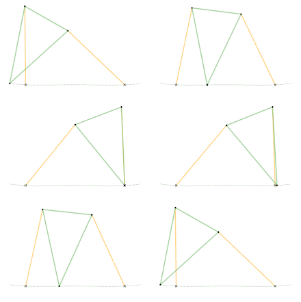
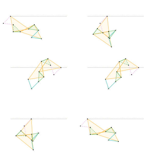
Links of the same color are the same length.
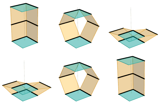
Parts of the same color are the same dimensions.

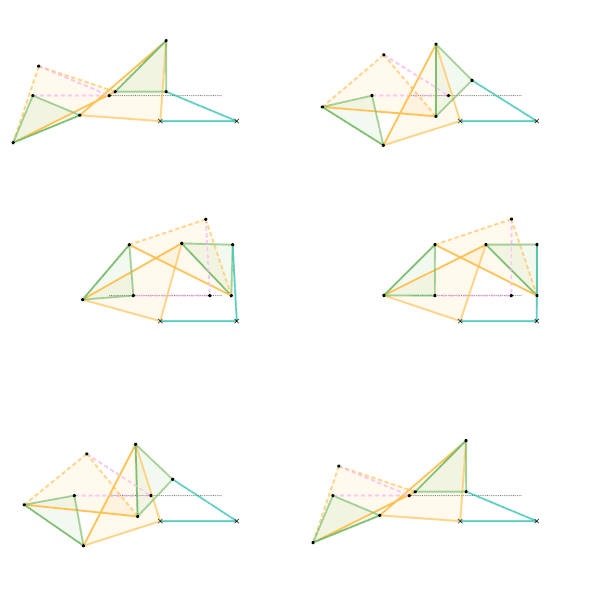
Links of the same color are the same length.
A straight-line mechanism is a mechanism that converts any type of rotary or angular motion to perfect or near-perfect straight-line motion, or vice versa. Straight-line motion is linear motion of definite length or "stroke", every forward stroke being followed by a return stroke, giving reciprocating motion. The first such mechanism, patented in 1784 by James Watt, produced approximate straight-line motion, referred to by Watt as parallel motion.
Straight-line mechanisms are used in a variety of applications, such as engines, vehicle suspensions, walking robots, and rover wheels.
History
In the late eighteenth century, before the development of the planer and the milling machine, it was extremely difficult to machine straight, flat surfaces. During that era, much thought was given to the problem of attaining a straight-line motion, as this would allow the flat surfaces to be machined. To find a solution to the problem, the first straight line mechanism was developed by James Watt, for guiding the piston of early steam engines. Although it does not generate an exact straight line, a good approximation is achieved over a considerable distance of travel.
Perfect straight line linkages were later discovered in the nineteenth century, but they weren't as needed, as by then other techniques for machining had been developed.
List of linkages
Approximate straight line linkages
These mechanisms often utilize four bar linkages as they require very few pieces. These four-bar linkages have coupler curves that have one or more regions of approximately perfect straight line motion. The exception in this list is Watt's parallel motion, which combines Watt's linkage with another four-bar linkage – the pantograph – to amplify the existing approximate straight line movement.
It is not possible to create perfectly straight line motion using a four-bar linkage, without using a prismatic joint.
- Watt's linkage (1784)
- Watt's parallel motion (1784)
- Evans "Grasshopper" linkage (1801)
- Chebyshev linkage
- Chebyshev lambda linkage (1878) - a cognate linkage of the Chebyshev linkage
- Roberts linkage
- Horse-head linkage
- Hoecken linkage (1926) - requires a sliding joint
Perfect straight line linkages
Eventually, perfect straight line motion would be achieved.
The Sarrus linkage was the first perfect linear linkage, made in 1853. However, it is a spatial linkage rather than a planar linkage. The first planar linkage would not be made until 1864.
Currently, all planar linkages which produce perfect linear motion utilize the inversion around a circle to produce a hypothetical circle of infinite radius, which is a line. This is why they are called inversors or inversor cells.
The simplest solutions are Hart's W-frame – which use 6-bars – and the Quadruplanar inversors – Sylvester-Kempe and Kumara-Kampling, which also use 6-bars.
- Sarrus linkage (1853)
- Peaucellier-Lipkin inversor (1864)
- Hart's first inversor / Hart's antiparallelogram / Hart's W-frame (1874)
- Hart's second inversor / Hart's A-frame (1875)
- Perrolatz inversor
- Kempe's double kite inversors[1] (1875)
- Bricard inversor[2]
- Quadruplanar inversor (1875)
The Scott Russell linkage (1803) translates linear motion through a right angle, but is not a straight line mechanism in itself. The Grasshopper beam/Evans linkage, an approximate straight line linkage, and the Bricard linkage, an exact straight line linkage, share similarities with the Scott Russell linkage and the Trammel of Archimedes.
Compound eccentric mechanisms with elliptical motion
These mechanisms use the principle of a rolling curve instead of a coupler curve and can convert continuous, rather than just limited, rotary motion to reciprocating motion and vice versa via elliptical motion. The straight-line sinusoidal motion produces no second-order inertial forces, which simplifies balancing in high-speed machines.
- Cardan straight line mechanism. Using the principle of the Tusi couple (1247), a spur gear rolls inside an internally toothed ring gear of twice the diameter. The hypocycloid traced by any point on the pitch circle of the smaller gear is a diameter of the larger gear. The mechanism has been used in Murray's Hypocyclic Engine.
- Trammel of Archimedes. Originally an ellipsograph. As a mechanism, it uses the fact that a circle and a straight line are special cases of an ellipse. It is based on much the same kinematic principle as Cardan's straight line mechanism (above) and could be considered as a spur gear with two teeth in a ring gear with four teeth. It has been used in the Baker-Cross engine.[3] It has been used in inverted form in Parsons' steam engine[4] and can still be found today in a further inversion as the Oldham coupling.
- MultiFAZE mechanism.[5] The Multiple Fixed Axis Shaft Compound Eccentric mechanism also uses elliptical motion, but here it is converted to rotary motion by an eccentric gear train instead of a double-load bearing with dimensional constraints, to reduce friction and wear. The mechanism has been used in a floating cantilever configuration in the Stiller-Smith engine[6][7] (see Gallery).
Gallery
Approximate straight line linkages
Parts/links of the same color are the same dimensions.
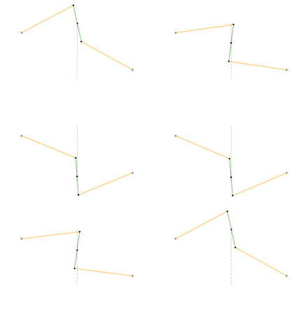 Watt's linkage
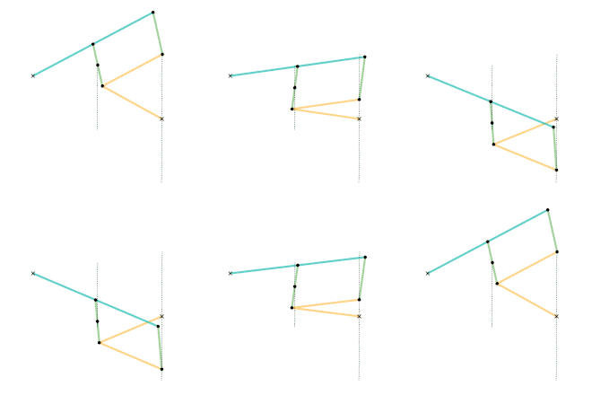 Watts parallel motion linkage
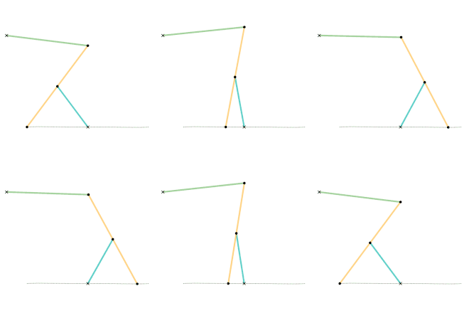 Evans "Grasshopper" linkage
 Roberts linkage
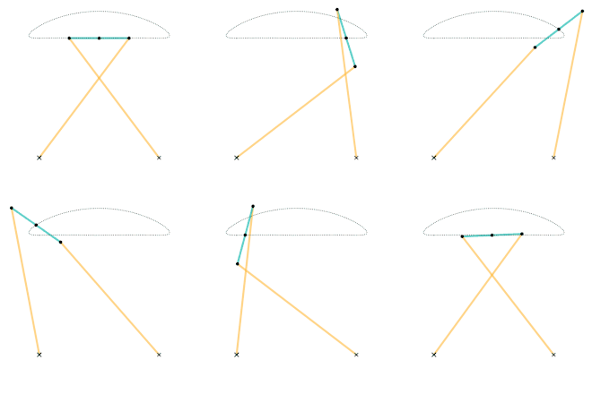 Chebyshev linkage
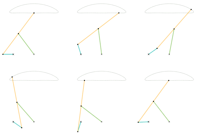 Chebyshev lambda linkage
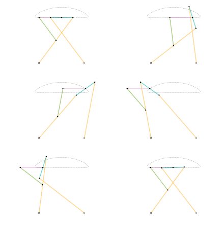 Chebyshev table linkage
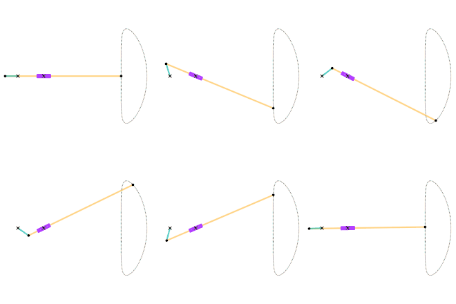 Hoecken's linkage
Perfect straight line linkages
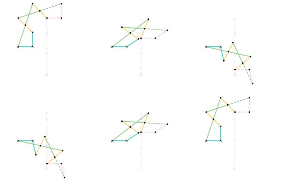
Parts/links of the same color are the same dimensions.
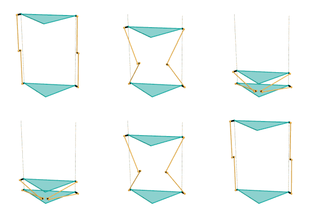 Sarrus linkage (Bars variant)
 Sarrus linkage (Plates variant)
 Peaucellier-Lipkin inversor
 Harts inversor 1
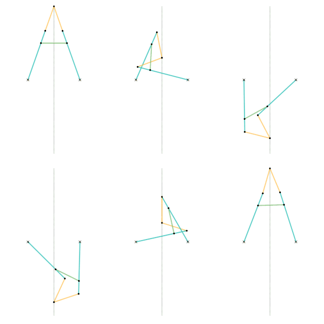 Harts inversor 2 [Note 1]
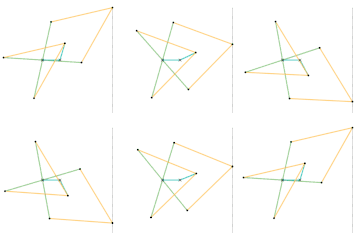 Perrolatz inversor
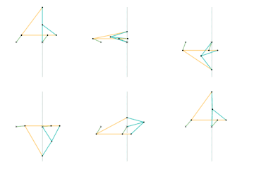 Kempe kite inversor 1 [Note 1]
 Kempe kite inversor 2 [Note 1]
 Kempe kite inversor 3 [Note 1]
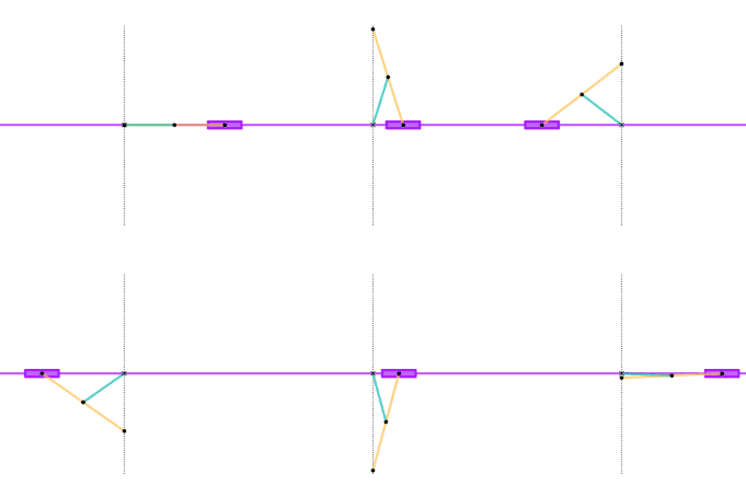 Scott Russell linkage (slider connection) [Note 1]
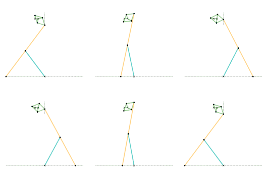 Scott Russell linkage (connected to Peaucellier-Lipkin linkage)
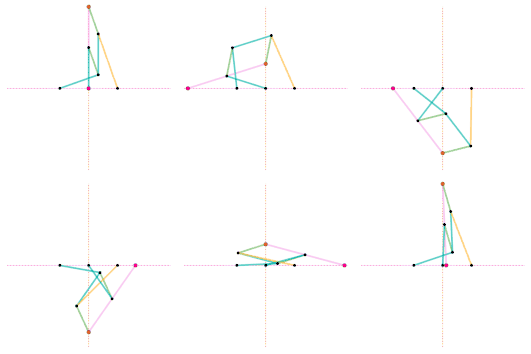 Bricard inversor [Note 1]
 Sylvester-Kempe quadruplanar inversor 1 [Note 1]
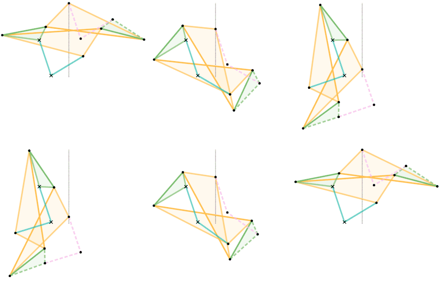 Sylvester-Kempe quadruplanar inversor 2 [Note 1]
 Sylvester-Kempe quadruplanar inversor 3
 Kumara-Kampling inversor [Note 1]
Tusi couple, elliptical motion: versions and inversions
 Tusi couple according to the diagrams in the translation of the copy of Tusi's original description: Small circle rolls within large circle.
 Tusi couple according to the translation of the copy of Tusi's original description: Circles rotate in same direction, speed ratio 2:1.
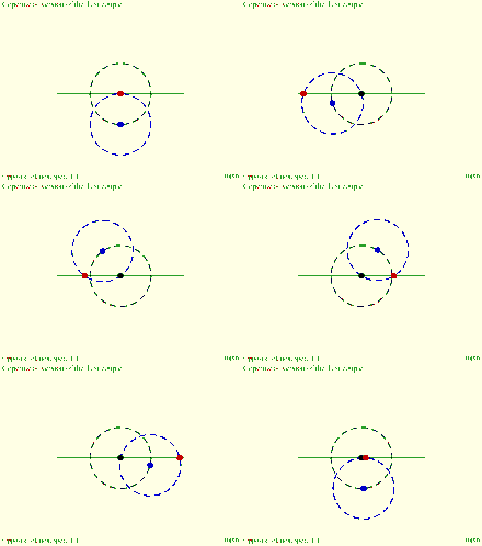 Copernicus' take on the Tusi couple: Direction of rotation and orbit of moving circle are equal and opposite.
 Inversion No. 3
 Inversion No. 4
 Parsons' mechanism is a doubled-up version of Tusi couple Inversion No. 2 linked by an Archimedes trammel.
 Oldham coupling. Slot- ted ends of two shafts (black) are coupled by cross piece (green). Compare with Tusi couple Inversion No. 4.
 Kinematics of the MultiFAZE mechanism characterised by parallelogram ABCD. The large broken circle is for reference only.
Compound eccentric mechanisms with elliptical motion
 A spur gear with two teeth rolls inside a ring gear with four teeth: Archimedes, Tusi or Cardano?
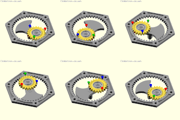 Cardan's hypocyclic gear pair: the red, green and blue pins move in straight lines.
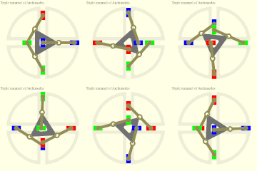 Three Archimedes trammels on a triangular rotor showing the circular orbit of the trammel midpoints.
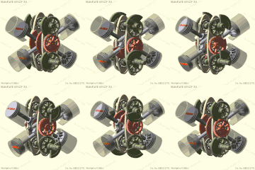 60° X4 engine with MultiFAZE mechanism with counterweights for full balance.
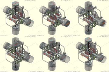 MultiFAZE 90° X4 engine with crossheads, trammel gears, and reciprocating balance weights/sliders.
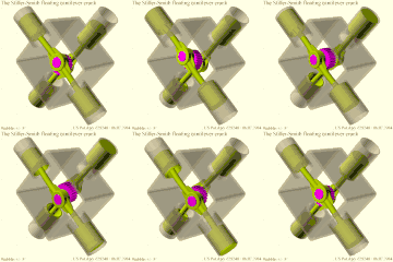 Stiller-Smith floating cantilever crank principle. Simulated wobble and overshoot exaggerated for effect.
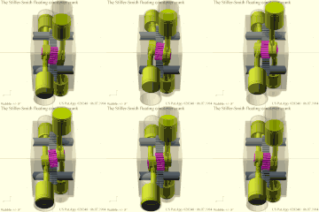 Stiller-Smith floating cantilever crank engine side view
See also
Notes
References
- ↑ Kempe, Alfred Bray (1877). How to Draw a Straight Line: A Lecture on Linkages. Macmillan and Company. ISBN 978-1-4297-0244-7.
- ↑ Artobolevsky, Ivan Ivanovich. Mechanisms in modern engineering design. ISBN 978-5-9710-5698-0.
- ↑ Four-cylinder, Four-cycle Engine With Two Reciprocating Components, A.J.S Baker, M.E Cross, The Institution of Mechanical Engineers, Automobile Division, Volume 188 38/74
- ↑ Parsons' epicyclic engine
- ↑ Patent No. DE 3232974, published March 1984
- ↑ Patent Application No. US 628 248, July 1984 (see US 4 641 611)
- ↑ Clean engines - A combination of advanced materials and a new engine design
- Theory of Machines and Mechanisms, Joseph Edward Shigley
External links
- Cornell university (archived) - Straight-line mechanism models
- Alfred Kempe (1877). How to Draw a Straight Line (PDF). Macmillan – via University of California at Irvine.
- Daina Taimina. "How to Draw a Straight Line - a tutorial". Cornell University.
- Simulations using the Molecular Workbench software
- bham.ac.uk - Hart's A-frame (draggable animation) 6-bar linkage