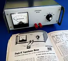
A capacitance meter is a piece of electronic test equipment used to measure capacitance, mainly of discrete capacitors. Depending on the sophistication of the meter, it may display the capacitance only, or it may also measure a number of other parameters such as leakage, equivalent series resistance (ESR), and inductance. For most purposes and in most cases the capacitor must be disconnected from circuit; ESR can usually be measured in circuit.
Simple checks without a true capacitance meter
Some checks can be made without a specialised instrument, particularly on aluminium electrolytic capacitors which tend to be of high capacitance and to be subject to poor leakage. A multimeter in a resistance range can detect a short-circuited capacitor (very low resistance) or one with very high leakage (high resistance, but lower than it should be; an ideal capacitor has infinite DC resistance). A crude idea of the capacitance can be derived with an analog multimeter in a high resistance range by observing the needle when first connected; current will flow to charge the capacitor and the needle will "kick" from infinite indicated resistance to a relatively low value, and then drift up to infinity. The amplitude of the kick is an indication of capacitance. Interpreting results requires some experience, or comparison with a good capacitor, and depends upon the particular meter and range used.
Simple and non-bridge meters
Many DVMs (digital volt meters) have a capacitance-measuring function. These usually operate by charging and discharging the capacitor under test with a known current and measuring the rate of rise of the resulting voltage; the slower the rate of rise, the larger the capacitance. DVMs can usually measure capacitance from nanofarads to a few hundred microfarads, but wider ranges are not unusual.
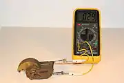
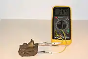
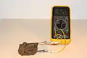
- Measurement the capacity of rotary capacitor with digital multimeter
 Cmin = 29 pF
 C = 269 pF
 Cmax = 520 pF
It is also possible to measure capacitance by passing a known high-frequency alternating current through the device under test and measuring the resulting voltage across it (does not work for polarised capacitors).
When troubleshooting circuit problems, a few problems are intermittent or only show up with the working voltage applied, and are not revealed by measurements with equipment, however sophisticated, which uses low test voltages. Some problems are revealed by using a "freezer" spray and observing the effect on circuit operation. Ultimately, in difficult cases routine replacement of capacitors (relatively cheap components) is easier than arranging measurements of all relevant parameters in working conditions.
Some more specialised instruments measure capacitance over a wide range using the techniques described above, and can also measure other parameters. Low stray and parasitic capacitance can be measured if a low enough range is available. Leakage current is measured by applying a direct voltage and measuring the current in the normal way.
Bridges

More sophisticated instruments use other techniques such as inserting the capacitor-under-test into a bridge circuit. By varying the values of the other legs in the bridge (so as to bring the bridge into balance), the value of the unknown capacitor is determined. This method of indirect use of measuring capacitance ensures greater precision. The bridge usually can also measure series resistance and inductance. Through the use of Kelvin connections and other careful design techniques, these instruments can usually measure capacitors over a range from picofarads to farads. Combined LCR meters that can measure inductance, resistance, and capacitance are available.
Bridge circuits do not themselves measure leakage current, but a DC bias voltage can be applied and the leakage measured directly.
Modern bridge instruments usually include a digital display and, where relevant, some sort of go/no go testing to allow simple automated use in a production environment. As with all modern instruments, bridges can be interfaced to computer and other equipment to export readings and allow external control.