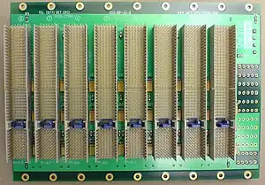
CompactPCI is a computer bus interconnect for industrial computers,[1] combining a Eurocard-type connector and PCI signaling and protocols. Boards are standardized to 3U or 6U sizes, and are typically interconnected via a passive backplane. The connector pin assignments are standardized by the PICMG US and PICMG Europe organizations. The connectors and the electrical rules allow for eight boards in a PCI segment. Multiple bus segments are allowed with bridges.[2]
Unlike the original Eurocard solutions such as VME, which use connectors with a 0.1 inch (2.54 mm) pin spacing, CompactPCI cards use metric connectors with a 2-millimeter pin spacing, designed to the IEC 1076 standard. 3U boards have a 110-pin connector (J1), which carries the 32-bit PCI bus signals, and an optional 110-pin connector (J2), which carries either user-defined I/O or the upper 32 bits of an optional 64-bit PCI bus. 6U cards have an identical J1, a J2 that is always used for 64-bit PCI, as well as J3, J4, and J5 connectors for a variety of uses either as user-defined I/O or specified signaling such as Telephony and/or Ethernet signaling. Hot-plugging is a supported feature of CompactPCI. Some of the pins are slightly longer to provide proper grounding when devices are inserted and removed.
The backplanes can be designed for 3.3 V VIO or 5 V VIO operation. These are differentiated by having 'Cadmium Yellow' coloured key for 3.3V or 'Brilliant Blue' colour for 5V operation. If the CompactPCI card operates on a particular VIO voltage the card shall have the respective coloured coding key. If the card is compatible with both voltages then it may not have any coding key. The image above illustrates a 5 V VIO 8-slot backplane.
CompactPCI was initially ratified as PICMG 2.0 in late 1995 as a passive backplane for PCI signaling. The 2.x series of specifications from PICMG provide support for a variety of technologies including Hot Swap (PICMG 2.1), Telephony signaling (PICMG 2.5) and most notably the expansion of the architecture to include switched Ethernet (PICMG 2.16).
Originally designed to support the PCI signaling protocol (and hence the name "CompactPCI"), CompactPCI has grown to include a variety of technologies centered on the application of the 2mm HM connector on the 3U and 6U form factor. In fact many systems are implemented with no PCI bus on the backplane, such as those implemented with switched Ethernet board interconnection (PICMG 2.16).
A drawback of the design is that the signal pins can become bent when a new device is inserted.
Related standards include CompactPCI Express and CompactPXI, which follow a similar concept, but substitute the protocols and signaling of PCI Express and PXI respectively.
The abbreviations cPCI, CPCI, cPCIe, and CPCIe are colloquial terms and are not officially used by PICMG.
See also
References
- ↑ "PICMG CompactPCI". PICMG. Retrieved 2015-03-19.
- ↑ "CompactPCI AdvancedTCA & MicroTCA Systems". OpenSystems Media. Archived from the original on 2006-02-05. Retrieved 2006-12-10.