Synchronous and asynchronous transmissions are two different methods of transmission synchronization. Synchronous transmissions are synchronized by an external clock, while asynchronous transmissions are synchronized by special signals along the transmission medium.[1]
The need for synchronization
Whenever an electronic device transmits digital (and sometimes analogue) data to another, there must be a certain rhythm established between the two devices, i.e., the receiving device must have some way of, within the context of the fluctuating signal that it's receiving, determining where each unit of data begins and where it ends.
Methods of synchronization
There are two ways to synchronize the two ends of the communication.
The synchronous signalling methods use two different signals. A pulse on one signal indicates when another bit of information is ready on the other signal.
The asynchronous signalling methods use only one signal. The receiver uses transitions on that signal to figure out the transmitter bit rate ("autobaud") and timing, and set a local clock to the proper timing, typically using a phase-locked loop (PLL) to synchronize with the transmission rate. A pulse from the local clock indicates when another bit is ready.
Synchronous transmission
In synchronous communications, the stream of data to be transferred is encoded as fluctuating voltage levels in one wire (the 'DATA'), and a periodic pulse of voltage on a separate wire (called the "CLOCK" or "STROBE") which tells the receiver "the current DATA bit is 'valid' at this moment in time".
Practically all parallel communications protocols use synchronous transmission. For example, in a computer, address information is transmitted synchronously—the address bits over the address bus, and the read or write strobes of the control bus.

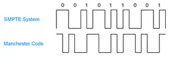
A logical one is indicated when there are two transitions in the same time frame as a zero. In the Manchester coding a transition from low to high indicates a one and a transition from high to low indicates a zero. When there are successive ones or zeros, an opposite transition is required on the edge of the time frame to prepare for the next transition and signal.
Asynchronous transmission
The most common asynchronous signalling, asynchronous start-stop signalling, uses a near-constant 'bit' timing (+/- 5% local oscillator required at both ends of the connection[2]). Using this method, the receiver detects the 'first' edge transition... (the START bit), waits 'half a bit duration' and then reads the value of the signal. A further delay of one 'whole bit duration' is executed before the next data bit is 'read' - repeating for the length of the whole serial word (typically 7/8-data bits). An optional PARITY bit follows the data bits and precedes the stop bit(s). Finally, one or more STOP bits are appended to identify the end of the data word and to make sure there is a bit transition when the next START bit is transmitted.
The word structure used in typical asynchronous serial communications is START-DATA[0:7]-PARITY[optional;0]-STOP[0:1]. These formatting variables are specified when configuring the transmit and receive nodes before communications take place. The bit duration is determined from the nominated bit rate in bits per second (bit/s) ... 300, 1200, 9600, 19200, 115200 etc. The use of the word BAUD is not strictly correct in the modern application of serial channels.
Special level & timing conditions are detected to identify an open-circuit condition (BREAK).
References
- ↑ "Synchronous vs. Asynchronous". www.engr.iupui.edu. Retrieved 2017-01-26.
- ↑ "Determining Clock Accuracy Requirements for UART Communications" (pdf). an2141. Maxim Integrated. 2003-08-07. Retrieved 1 November 2021.