A compensation winding in a DC shunt motor is a winding in the field pole face plate that carries armature current to reduce stator field distortion. Its purpose is to reduce brush arcing and erosion in DC motors that are operated with weak fields, variable heavy loads or reversing operation such as steel-mill motors. When flux from the armature current is about equal to the flux from the field current, the flux at the field pole plate is shifted. Under a fixed load, there is an optimal commutation point for the brushes that minimizes arcing and erosion of the brushes. When the ratio of armature flux to field flux varies greatly or reverses, the optimum commutation point shifts as result of the varying flux at the pole face plate. The result is arcing of the brushes. By adding a compensating winding in the pole face plate that carries armature current in the opposite direction of current in the adjacent armature windings, the position of the flux at the pole face plate can be restored to the position it would have with zero armature current. The main drawback of a compensation winding is the expense.[1]: 393 [2]: 65–66
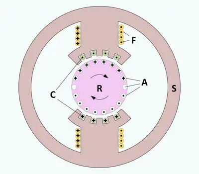 A. Cross section of DC motor with compensation windings. A = armature windings, C = compensation windings, F = field windings, R = rotor (armature), S = stator (field). |
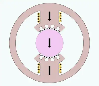 B. Cross section of DC motor with compensation windings showing magnetic flux due to field windings. |
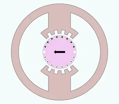 C. Cross section of DC motor with compensation windings showing magnetic flux due to armature windings. |
Figure A. shows a cross-sectional view of a two pole DC shunt motor. Armature windings (A), field windings (F) and compensation windings (C) use the dot and cross convention where a circle with a dot is a wire carrying current out of the figure and a circle with a cross is a wire carrying current into the page. For each wire in the armature that is next to the field pole face plate there is a wire in the face plate carrying current in the opposite direction.
Figure B. shows the flux caused by the field winding alone.
Figure C. shows the flux caused by the armature winding alone.
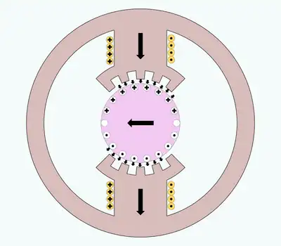 D. Cross section of DC motor with compensation windings showing magnetic flux due to field and armature under heavy load. The flux in the gap has shifted. |
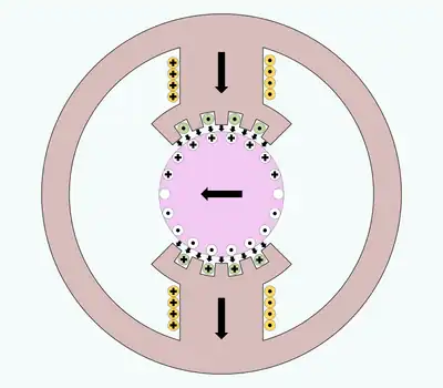 E. Cross section of DC motor with compensation windings showing magnetic flux due to field and armature under heavy load with compensation windings. The flux in the gap has been restored. |
Figure D. shows field flux and armature flux being about equal. The result is that the center of flux in the gap between the pole face plate and the armature has shifted. For a more detailed drawing, see Richardson. [3]: 66
Figure E. shows compensation wires in the field pole face plate that are carrying current opposed to the current in the armature wire adjacent to the gap. The flux in the gap has been restored to the same condition as the case where there is no armature flux. Even though the armature wires are next to wires carrying current in the opposite direction, the wires of the armature still experience magnetic force from interaction with the field flux.
References
- ↑ Fitzgerald, A. E.; Kingsley, Charles Jr.; Umans, Stepen D. (2003), Electric Machinery (6th ed.), Tata McGraw-Hill, ISBN 978-0-07-053039-3
- ↑ Richardson, Donald V. (1978), Rotating Electric Machinery and Transformer Technolog, Reston Publishing, ISBN 0-87909-732-9
- ↑ Richardson, Donald V. (1978), Rotating Electric Machinery and Transformer Technolog, Reston Publishing, ISBN 0-87909-732-9