A crowbar circuit is an electrical circuit used for preventing an overvoltage or surge condition of a power supply unit from damaging the circuits attached to the power supply. It operates by putting a short circuit or low resistance path across the voltage output (Vo), like dropping a crowbar across the output terminals of the power supply. Crowbar circuits are frequently implemented using a thyristor, TRIAC, trisil or thyratron as the shorting device. Once triggered, they depend on the current-limiting circuitry of the power supply or, if that fails, the blowing of the line fuse or tripping the circuit breaker.
The name is derived from having the same effect as throwing a crowbar over exposed power supply terminals to short the output.
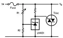
An example crowbar circuit is shown to the right. This particular circuit uses an LM431 adjustable zener regulator to control the gate of the TRIAC. The resistor divider of R1 and R2 provide the reference voltage for the LM431. The divider is set so that during normal operating conditions, the voltage across R2 is slightly lower than VREF of the LM431. Since this voltage is below the minimum reference voltage of the LM431, it remains off and very little current is conducted through the LM431. If the cathode resistor is sized accordingly, very little voltage will be dropped across it and the TRIAC gate terminal will be essentially at the same potential as MT1, keeping the TRIAC off. If the supply voltage increases, the voltage across R2 will exceed VREF and the LM431 cathode will begin to draw current. The voltage at the gate terminal will be pulled down, exceeding the gate trigger voltage of the TRIAC and latching it on.
Overview
A crowbar circuit is distinct from a clamp in pulling, once triggered, the voltage below the trigger level, usually close to ground voltage. A clamp prevents the voltage from exceeding a preset level. Thus, a crowbar will not automatically return to normal operation when the overvoltage condition is removed; power must be removed entirely to allow the crowbar to return to its neutral state.
An active crowbar is a crowbar that can remove the short circuit when the transient is over thus allowing the device to resume normal operation. Active crowbars use a transistor, gate turn off (GTO) thyristor or forced commutated thyristor instead of a thyristor to short the circuit. Active crowbars are commonly used to protect the frequency converter in the rotor circuit of doubly fed generators against high voltage and current transients caused by the voltage dips in the power network. Thus the generator can ride through the fault and quickly continue the operation even during the voltage dip.
The advantage of a crowbar over a clamp is that the low holding voltage of the crowbar lets it carry higher fault current without dissipating much power (which could otherwise cause overheating). Also, a crowbar is more likely than a clamp to deactivate a device (by blowing a fuse or tripping a breaker), bringing attention to the faulty equipment.
The term is also used as a verb to describe the act of short-circuiting the output of a power supply, or the malfunction of a CMOS circuit -- the PMOS half of a pair lingering in a near on-state when only its corresponding NMOS is supposed to be on (or the NMOS when the PMOS is supposed to be on) -- resulting in a near short-circuit current between supply rails.
Applications
High voltage crowbars are used for HV tube (klystron and IOT) protection.
Many bench top power supplies have a crowbar circuit to protect the connected equipment.
Microwave ovens often use a microswitch that acts as a crowbar circuit in the door latch assembly. This monitor switch will absolutely prevent the magnetron from being energized with the door open by short circuiting the mains supply to the magnetron. Applying power with the monitor switch closed will blow the main fuse and ruin the microswitch.[1]
See also
References
- ↑ "How does the Monitor Switch in a Microwave Work?". 18 May 2021.
Further reading
- Paul Horowitz and Winfield Hill, The Art of Electronics, Third Edition, pages 598,690-691, Cambridge University Press, 2015.
- Paul Horowitz and Winfield Hill, The Art of Electronics The X Chapters, First Edition, pages 353,393,395,412,413, Cambridge University Press, 2020.
- Paul Scherz and Simon Monk, Practical Electronics for Inventors, Fourth Edition, pages 710, Cambridge University Press, 2016.
- Paul Horowitz and Winfield Hill, The Art of Electronics, Second Edition, pages 318-319, Cambridge University Press, 1989.