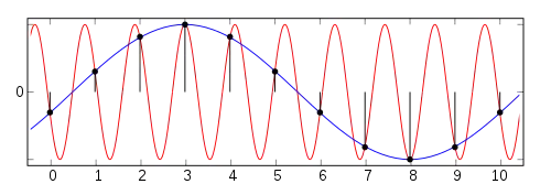
Frequency ambiguity resolution is used to find the true target velocity for medium pulse repetition frequency (PRF) radar systems. This is used with pulse-Doppler radar.
Definition
Radial velocity aliasing occurs when reflections arrive from reflectors moving fast enough for the Doppler frequency to exceed the pulse repetition frequency (PRF).
Frequency ambiguity resolution is required to obtain the true radial velocity when the measurements is made using a system where the following inequality is true.
The radial velocity measurements made in this way produce a modulo function of the true radial velocity.
Theory
Radar pulsing causes a phenomenon called aliasing, which occurs when the Doppler frequency created by reflector motion exceeds the pulse repetition frequency (PRF).[1]
This concept is related to range ambiguity resolution.
Doppler frequency shift is introduced onto reflected signals used by radar.
Operation
When the Doppler frequency shift exceeds the PRF, the frequency is reduced. This limitation is called the Nyquist sampling rate. This introduces a modulo operation onto the apparent frequency of the reflected signal.
The ambiguous velocity is as follows.
Frequency is folded for high speed targets where radial velocity produces a frequency shift above the Nyquist frequency. The true speed of the target may be folded by a modulo operation produced by the sampling process.
The Nyquist frequency will also change when the PRF is changed.
This is explained best using an example with 2 different PRF, although real systems use a different method.
In the example, PRF A can detect true speed up to 600MPH and PRF B can detect true speed up to 500MPH.
| 0MPH | 100MPH | 200MPH | 300MPH | 400MPH | 500MPH |
|---|---|---|---|---|---|
| Target PRF A | |||||
| Target PRF B |
The apparent speed for PRF A falls in the 200MPH filter, and the apparent speed for PRF B falls in the 400MPH filter. This combination places the true target speed at 1,400MPH (2x6+2 or 2x5+4). This can be seen graphically when range intervals are stacked end-to-end as shown below.
| 0 | 1 | 2 | 3 | 4 | 5 | 6 | 7 | 8 | 9 | 10 | 11 | 12 | 13 | 14 | 15 | 16 | 17 | 18 | 19 | 20 | 21 | 22 | 23 | 24 | 25 | 26 | 27 | 29 | 29 |
|---|---|---|---|---|---|---|---|---|---|---|---|---|---|---|---|---|---|---|---|---|---|---|---|---|---|---|---|---|---|
| A | A | A | A | A | |||||||||||||||||||||||||
| B | B | B | B | B | B |
"A" represents target speed possibilities for PRF A, and "B" represents target speed possibilities for PRF B.
This frequency ambiguity resolution signal processing technique determines true velocity.
Ambiguity resolution is typically implemented with a look-up table. This could also be implemented as a convolution function, where the spectrum amplitudes from one PRF are applied to spectrum samples from the other PRF as a sliding window function.[2]
Limitations
Processing techniques are slightly more complicated when there is more than one reflection at the same distance with slightly different radial velocity.
References
- ↑ "Sampling and Aliasing". Curtin University of Technology. Archived from the original on 2011-07-27. Retrieved 2011-08-03.
- ↑ "Sliding Window". Radartutorial.