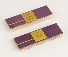
A Peripheral Interface Adapter (PIA) is a peripheral integrated circuit providing parallel I/O interfacing for microprocessor systems.

<span style="color:
#626971;">    ┌─────⊔︀─────┐
Vss ┤ 1       40├ CA1
PA0 ┤ 2       39├ CA2
PA1 ┤ 3       38├ !IRQA
PA2 ┤ 4       37├ !IRQB
PA3 ┤ 5       36├ RS0
PA4 ┤ 6       35├ RS1
PA5 ┤ 7       34├ !RES
PA6 ┤ 8       33├ D0
PA7 ┤ 9       32├ D1
PB0 ┤10       31├ D2
PB1 ┤11       30├ D3
PB2 ┤12       29├ D4
PB3 ┤13       28├ D5
PB4 ┤14       27├ D6
PB5 ┤15       26├ D7
PB6 ┤16       25├ E
PB7 ┤17       24├ CS1
CB1 ┤18       23├ !CS2
CB2 ┤19       22├ CS0
Vcc ┤20       21├ R/!W
    └───────────┘</span>
Description
Common PIAs include the Motorola MC6820 and MC6821, and the MOS Technology MCS6520, all of which are functionally identical but have slightly different electrical characteristics. The PIA is most commonly packaged in a 40 pin DIP package.
The PIA is designed for glueless connection to the Motorola 6800 style bus, and provides 20 I/O lines, which are organised into two 8-bit bidirectional ports (or 16 general-purpose I/O lines) and 4 control lines (for handshaking and interrupt generation). The directions for all 16 general lines (PA0-7, PB0-7) can be programmed independently. The control lines can be programmed to generate interrupts, automatically generate handshaking signals for devices on the I/O ports, or output a plain high or low signal.
In 1976 Motorola switched the MC6800 family to a depletion-mode technology to improve the manufacturing yield and to operate at a faster speed. The Peripheral Interface Adapter had a slight change in the electrical characteristics of the I/O pins so the MC6820 became the MC6821.[1]
The MC6820 was used in the Apple I to interface the ASCII keyboard and the display.[2] It was also deployed in the 6800-powered first generation of Bally electronic pinball machines (1977-1985), such as Flash Gordon[3] and Kiss.[4] The MCS6520 was used in the Atari 400 and 800[5] and Commodore PET[6] family of computers (for example, to provide four joystick ports to the machine). The Tandy Color Computer uses two MC6821s to provide I/O access to the video, audio and peripherals.[7]
References
- Leventhal, Lance A. (1986). 6502 Assembly Language Programming 2nd Edition. Osborne/McGraw-Hill. ISBN 0-07-881216-X.
- ↑ Advanced Information: 1.5 and 2.0 MHz Components for the M6800 Microcomputer System. Austin, Texas: Motorola Semiconductor Products. April 1977. pp. 4–6. ADI-429. The MC6820 became the MC6821 because the electrical characteristic of PA0–7 and PB0–7 pins changed slightly. The typical Input High Current went from -250 μAdc to -400 μAdc and the Input Low Current went from 1.0 mAdc to 1.3 mAdc.
- ↑ Apple-1 Operation Manual (PDF). 1976. p. 7. Archived from the original (PDF) on 2011-05-19. Retrieved 2016-03-05.
- ↑ Flash Gordon Manual. Bally. 1981. p. 22.
- ↑ Kiss Manual. Bally. 1979. p. 22.
- ↑ Sams Computerfacts Technical Service Data - Atari 800 (PDF). November 1984. p. IV.
- ↑ West, Raeto Collin (January 1982). Programming the PET/CBM. COMPUTE! Books. ISBN 0-942386-04-3. Retrieved 2020-04-05.
- ↑ Chris Lomont (July 2006). "Chris Lomont's Color Computer 1/2/3 Hardware Programming" (PDF). www.lomont.org/Software/Misc/CoCo/Lomont_CoCoHardware.pdf. Retrieved 5 May 2020.