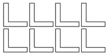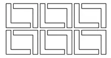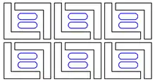


In manufacturing industry, nesting refers to the process of laying out cutting patterns to minimize the raw material waste.[1] Examples include manufacturing parts from flat raw material such as sheet metal, glass sheets, cloth rolls, cutting parts from steel bars, etc.
Such process can also be applied to additive manufacturing, such as 3D printing. Here the advantages sought can include minimizing tool movement that is not producing product, or maximizing how many pieces can be fabricated in one build session. One difference from nesting of cut pieces is that 3D parts often have a cross section that changes with height, which can cause interference between adjacent parts as they are built up.
Types
The nesting process differs for different types of parts:
- 1D nesting - for cutting optimization of one-dimensional parts such as bars, trusses, wires, pipes, rails
- 2D nesting - for cutting optimization of flat parts such as sheet metal, cloth, glass, paper, leather
- nesting of rectangular shapes vs. nesting of multiple freeform 2D shapes (optionally with holes/isles)
- nesting from fixed sheets vs. nesting from infinite rolls
- 3D nesting - for packing optimization of 3D parts such as boxes, shipping containers, 3D printed parts
- nesting/packing of freeform 3D objects
Process
To minimize the amount of scrap raw material produced during cutting, companies use nesting software.[1] It automates the calculation of ideal distribution of the cutting patterns to avoid waste.[2] The process involves the analyses the parts (shapes) to be produced at a particular time. Using algorithms, it then determines how to lay these parts out in such a way as to produce the required quantities of parts, while minimizing the amount of raw material (or space) wasted.
Off-the-shelf nesting software packages address the optimization needs. While some cater only to rectangular nesting, others offer profile or shape nesting where the parts required can be any odd shape. These irregular parts can be created using popular computer-aided design (CAD) tools. Here, the nesting software may be utilized as the connection between CAD drawings and the cut output.[3]
Most of the profile nesting software can read IGES or DXF profile files automatically, a few of them work with built-in converters. An important consideration in shape nesting is to verify that the software in question actually performs true profile nesting and not just block nesting (rectangular). In block nesting an imaginary rectangle is drawn around the shape and then the rectangles are laid side-by side which actually is not profile nesting. There remains scope for waste reduction.
Nesting software must take into account the limitations and features of the material and machining technology in use, such as:
- Machining cannot take place where the raw material is clamped into place;
- Some machines can access only half of the material at a particular time; the machine automatically flips the sheet over to allow the remaining half to be accessed;
- When punching, the width of the punch tool must be considered;
- Shearing may be permitted only in certain areas of the sheet due to limitations of the machinery (e.g. always across the whole sheet);
- Some cutting technologies (plasma) require some minimal offset between the parts;
Nesting software may also have to take into account material characteristics, such as:
- Defects on material that must be discarded;
- Different quality areas that must match corresponding quality levels required for different parts;
- Direction constraints, that may come from a printed pattern or from fiber direction (graining);
- Front and back sides of the raw material;
Many machine manufacturers offer their own custom nesting software designed to offer ease of use and take full advantage of the features of their specific machines.
If a fabricator operates machines from more than one vendor, they may prefer to use an off-the-shelf nesting software package from a third-party vendor. They then have the potential to run jobs on any available machine, and their staff should not have to learn several different software packages.
See also
Material may be cut using off-line blanking dies, lasers, plasma, punches, shear blades, ultrasonic knives and water jet cutters.
References
- 1 2 Naboni, Roberto; Paoletti, Ingrid (2015). Advanced Customization in Architectural Design and Construction. Cham: Springer. p. 163. ISBN 978-3-319-04422-4.
- ↑ Schmidt, Mario; Spieth, Hannes; Haubach, Christian; Kühne, Christian (2018). 100 Pioneers in Efficient Resource Management: Best practice cases from producing companies. Heidelberg: Springer. p. 486. ISBN 978-3-662-56744-9.
- ↑ Vilumsone-Nemes, Ineta (2018). Industrial Cutting of Textile Materials. Duxford, UK: Woodhead Publishing. p. 128. ISBN 978-0-08-102122-4.