The return ratio of a dependent source in a linear electrical circuit is the negative of the ratio of the current (voltage) returned to the site of the dependent source to the current (voltage) of a replacement independent source. The terms loop gain and return ratio are often used interchangeably; however, they are necessarily equivalent only in the case of a single feedback loop system with unilateral blocks.[1]
Calculating the return ratio

The steps for calculating the return ratio of a source are as follows:[2]
- Set all independent sources to zero.
- Select the dependent source for which the return ratio is sought.
- Place an independent source of the same type (voltage or current) and polarity in parallel with the selected dependent source.
- Move the dependent source to the side of the inserted source and cut the two leads joining the dependent source to the independent source.
- For a voltage source the return ratio is minus the ratio of the voltage across the dependent source divided by the voltage of the independent replacement source.
- For a current source, short-circuit the broken leads of the dependent source. The return ratio is minus the ratio of the resulting short-circuit current to the current of the independent replacement source.
Other Methods
These steps may not be feasible when the dependent sources inside the devices are not directly accessible, for example when using built-in "black box" SPICE models or when measuring the return ratio experimentally. For SPICE simulations, one potential workaround is to manually replace non-linear devices by their small-signal equivalent model, with exposed dependent sources. However this will have to be redone if the bias point changes.
A result by Rosenstark shows that return ratio can be calculated by breaking the loop at any unilateral point in the circuit. The problem is now finding how to break the loop without affecting the bias point and altering the results. Middlebrook[3] and Rosenstark[4] have proposed several methods for experimental evaluation of return ratio (loosely referred to by these authors as simply loop gain), and similar methods have been adapted for use in SPICE by Hurst.[5] See Spectrum user note or Roberts, or Sedra, and especially Tuinenga.[6][7][8]
Example: Collector-to-base biased bipolar amplifier

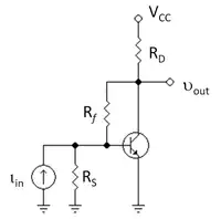
Figure 1 (top right) shows a bipolar amplifier with feedback bias resistor Rf driven by a Norton signal source. Figure 2 (left panel) shows the corresponding small-signal circuit obtained by replacing the transistor with its hybrid-pi model. The objective is to find the return ratio of the dependent current source in this amplifier.[9] To reach the objective, the steps outlined above are followed. Figure 2 (center panel) shows the application of these steps up to Step 4, with the dependent source moved to the left of the inserted source of value it, and the leads targeted for cutting marked with an x. Figure 2 (right panel) shows the circuit set up for calculation of the return ratio T, which is
The return current is
The feedback current in Rf is found by current division to be:
The base-emitter voltage vπ is then, from Ohm's law:
Consequently,
Application in asymptotic gain model
The overall transresistance gain of this amplifier can be shown to be:
with R1 = RS || rπ and R2 = RD || rO.
This expression can be rewritten in the form used by the asymptotic gain model, which expresses the overall gain of a feedback amplifier in terms of several independent factors that are often more easily derived separately than the overall gain itself, and that often provide insight into the circuit. This form is:
where the so-called asymptotic gain G∞ is the gain at infinite gm, namely:
and the so-called feed forward or direct feedthrough G0 is the gain for zero gm, namely:
For additional applications of this method, see asymptotic gain model and Blackman's theorem.
References
- ↑ Richard R Spencer & Ghausi MS (2003). Introduction to electronic circuit design. Upper Saddle River NJ: Prentice Hall/Pearson Education. p. 723. ISBN 0-201-36183-3.
- ↑ Paul R. Gray, Hurst P J Lewis S H & Meyer RG (2001). Analysis and design of analog integrated circuits (Fourth ed.). New York: Wiley. p. §8.8 pp. 599–613. ISBN 0-471-32168-0.
- ↑ Middlebrook, RD:Loop gain in feedback systems 1; Int. J. of Electronics, vol. 38, no. 4, (1975) pp. 485-512
- ↑ Rosenstark, Sol: Loop gain measurement in feedback amplifiers; Int. J. of Electronics, vol. 57, No. 3 (1984) pp. 415-421
- ↑ Hurst, PJ: Exact simulation of feedback circuit parameters; IEEE Trans. on Circuits and Systems, vol. 38, No. 11 (1991) pp.1382-1389
- ↑ Gordon W. Roberts & Sedra AS (1997). SPICE (Second ed.). New York: Oxford University Press. pp. Chapter 8, pp. 256–262. ISBN 0-19-510842-6.
- ↑ Adel S Sedra & Smith KC (2004). Microelectronic circuits (Fifth ed.). New York: Oxford University Press. pp. Example 8.7, pp. 855–859. ISBN 0-19-514251-9.
- ↑ Paul W Tuinenga (1995). SPICE: a guide to circuit simulation and analysis using PSpice (Third ed.). Englewood Cliffs NJ: Prentice-Hall. pp. Chapter 8: Loop gain analysis. ISBN 0-13-436049-4.
- ↑ Richard R Spencer & Ghausi MS (2003). Example 10.7 pp. 723-724. ISBN 0-201-36183-3.