A lightning detector is a device that detects lightning produced by thunderstorms. There are three primary types of detectors: ground-based systems using multiple antennas, mobile systems using a direction and a sense antenna in the same location (often aboard an aircraft), and space-based systems. The first such device was invented in 1894 by Alexander Stepanovich Popov. It was also the first radio receiver in the world.
Ground-based and mobile detectors calculate the direction and severity of lightning from the current location using radio direction-finding techniques along with an analysis of the characteristic frequencies emitted by lightning. Ground-based systems can use triangulation from multiple locations to determine distance, while mobile systems can estimate distance using signal frequency and attenuation. Space-based detectors on satellites can be used to locate lightning range, bearing and intensity by direct observation.
Ground-based lightning detector networks are used by meteorological services like the National Weather Service in the United States, the Meteorological Service of Canada, the European Cooperation for Lightning Detection (EUCLID), the Institute for Ubiquitous Meteorology (Ubimet) and by other organizations like electrical utilities and forest fire prevention services.

Limitations
Each system used for lightning detection has its own limitations.[2] These include
- A single ground-based lightning network must be able to detect a flash with at least three antennas to locate it with an acceptable margin of error. This often leads to the rejection of cloud-to-cloud lightning, as one antenna might detect the position of the flash on the starting cloud and the other antenna the receiving one. As a result, ground-based networks have a tendency to underestimate the number of flashes, especially at the beginning of storms where cloud-to-cloud lightning is prevalent.
- Ground-based systems that use multiple locations and time-of-flight detection methods must have a central device to collect strike and timing data to calculate location. In addition, each detection station must have a precision timing source that is used in the calculation.
- Since they use attenuation rather than triangulation, mobile detectors sometimes mistakenly indicate a weak lightning flash nearby as a strong one further away, or vice versa.
- Space-based lightning networks suffer from neither of these limitations, but the information provided by them is often several minutes old by the time it is widely available, making it of limited use for real-time applications such as air navigation.
Lightning detectors vs. weather radar


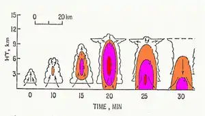
Lightning detectors and weather radar work together to detect storms. Lightning detectors indicate electrical activity, while weather radar indicates precipitation. Both phenomena are associated with thunderstorms and can help indicate storm strength.
- Air is moving upward due to instability.
- Condensation occurs and radar detects echoes above the ground (colored areas).
- Eventually, the mass of raindrops is too large to be sustained by the updraft and they fall toward the ground.
The cloud must develop to a certain vertical extent before lightning is produced, so generally, weather radar will indicate a developing storm before a lightning detector does. It is not always clear from early returns if a shower cloud will develop into a thunderstorm, and weather radar also sometimes suffers from a masking effect by attenuation, where precipitation close to the radar can hide (perhaps more intense) precipitation farther away. Lightning detectors do not suffer from a masking effect and can provide confirmation when a shower cloud has evolved into a thunderstorm.
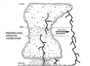
Lightning may also be located outside the precipitation recorded by radar. The second image shows that this happens when strikes originate in the anvil of the thundercloud (top part blown ahead of the cumulonimbus cloud by upper winds) or on the outside edge of the rain shaft. In both cases, there is still an area of radar echoes somewhere nearby.
Aviation use
Large airliners are more likely to use weather radar than lightning detectors, since weather radar can detect smaller storms that also cause turbulence; however, modern avionics systems often include lightning detection as well, for additional safety.
For smaller aircraft, especially in general aviation, there are two main brands of lightning detectors (often referred to as sferics, short for radio atmospherics): Stormscope, produced originally by Ryan (later B.F. Goodrich) and currently by L-3 Communications, and the Strikefinder, produced by Insight. Strikefinder can detect and properly display IC (intracloud) and CG (cloud to ground) strikes, as well as being able to differentiate between real strikes and signal bounces reflected off the Ionosphere. Lightning detectors are inexpensive and lightweight, making them attractive to owners of light aircraft (particularly of single-engine aircraft, where the aircraft nose is not available for installation of a radome).
Professional-quality portable lightning detectors

Inexpensive portable lightning detectors as well as other single sensor lightning mappers, such as those used on aircraft, have limitations including detection of false signals and poor sensitivity, particularly for intracloud (IC) lightning. Professional-quality portable lightning detectors improve performance in these areas by several techniques which facilitate each other, thus magnifying their effects:
- False signal elimination: A lightning discharge generates both a radio frequency (RF) electromagnetic signal – commonly experienced as "static" on an AM radio – and very short duration light pulses, comprising the visible "flash". A lightning detector that works by sensing just one of these signals may misinterpret signals coming from sources other than lightning, giving a false alarm. Specifically, RF-based detectors may misinterpret RF noise, also known as RF Interference or RFI. Such signals are generated by many common environmental sources, such as auto ignitions, fluorescent lights, TV sets, light switches, electric motors, and high voltage wires. Likewise, light-flash-based detectors may misinterpret flickering light generated in the environment, such as reflections from windows, sunlight through tree leaves, passing cars, TV sets, and fluorescent lights.
However, since RF signals and light pulses rarely occur simultaneously except when produced by lightning, RF sensors and light pulse sensors can usefully be connected in a "coincidence circuit" which requires both kinds of signals simultaneously in order to produce an output.[3] If such a system is pointed toward a cloud and lightning occurs in that cloud, both signals will be received; the coincidence circuit will produce an output; and the user can be sure the cause was lightning. When a lightning discharge occurs within a cloud at night, the entire cloud appears to illuminate. In daylight these intracloud flashes are rarely visible to the human eye; nevertheless, optical sensors can detect them. In early missions, astronauts used optical sensors to detect lightning in bright, sunlit clouds far below. This application led to the development of the dual signal portable lightning detector which utilizes light flashes as well as the "sferics" signals detected by previous devices.
- Improved Sensitivity: In the past, lightning detectors, both inexpensive portable ones for use on the ground and expensive aircraft systems, detected low frequency radiation because at low frequencies the signals generated by cloud-to-ground (CG) lightning are stronger (have higher amplitude) and thus are easier to detect. However, RF noise is also stronger at low frequencies. To minimize RF noise reception, low-frequency sensors are operated at low sensitivity (signal reception threshold) and thus do not detect less intense lightning signals. This reduces the ability to detect lightning at longer distances since signal intensity decreases with the square of distance. It also reduces detection of intracloud (IC) flashes which generally are weaker than CG flashes.
- Enhanced Intracloud Lightning Detection: The addition of an optical sensor and coincidence circuit not only eliminates false alarms caused by RF noise; it also allows the RF sensor to be operated at higher sensitivity and to sense higher frequencies characteristic of IC lightning and enable the weaker high frequency components of IC signals and more distant flashes to be detected.
The improvements described above significantly extend the detector's utility in many areas:
- Early warning: Detection of IC flashes is important because they typically occur from 5 to 30 minutes before CG flashes and so can provide earlier warning of developing thunderstorms , greatly enhancing the effectiveness of the detector in personal-safety and storm-spotting applications compared to a CG-only detector . Increased sensitivity also provides warning of already-developed storms which are more distant but may be moving toward the user.
- Storm location: Even in daylight, "storm chasers" can use directional optical detectors that can be pointed at an individual cloud to distinguish thunderclouds at a distance. This is particularly important for identifying the strongest thunderstorms which produce tornadoes, since such storms produce higher flash rates with more high frequency radiation than weaker non-tornadic storms.[4]: 248
- Microburst prediction: IC flash detection also provides a method for predicting microbursts.[5]: 46–47 The updraft in convective cells starts to become electrified when it reaches altitudes sufficiently cold so that mixed phase hydrometeors (water and ice particles) can exist in the same volume. Electrification occurs due to collisions between ice particles and water drops or water coated ice particles. The lighter ice particles (snow) are charged positively and carried to the upper portion of the cloud leaving behind the negatively charged water drops in the central part of the cloud.[6]: 6014 These two charge centers create an electric field leading to lightning formation. The updraft continues until all the liquid water is converted to ice, which releases latent heat driving the updraft. When all the water is converted, the updraft collapses rapidly as does the lightning rate. Thus the increase in lightning rate to a large value, mostly due to IC discharges, followed by a rapid dropoff in rate provides a characteristic signal of the collapse of the updraft which carries particles downward in a downburst. When the ice particles reach warmer temperatures near cloudbase they melt causing atmospheric cooling; likewise, the water drops evaporate, also causing cooling. This cooling increases air density which is the driving force for microbursts. The cool air in "gust fronts" often experienced near thunderstorms is caused by this mechanism.
- Storm identification/tracking: Some thunderstorms, identified by IC detection and observation, make no CG flashes and would not be detected with a CG sensing system. IC flashes also are many times as frequent [4]: 192 as CG so provide a more robust signal. The relative high density (number per unit area) of IC flashes allows convective cells to be identified when mapping lightning whereas CG lightning are too few and far between to identify cells which typically are about 5 km in diameter. In the late stages of a storm the CG flash activity subsides and the storm may appear to have ended—but generally there still is IC activity going on in the residue mid-altitude and higher cirrus anvil clouds, so the potential for CG lightning still exists.
- Storm intensity quantification: Another advantage of IC detection is that the flash rate (number per minute) is proportional to the 5th power of the convective velocity of the updrafts in the thundercloud.[6]: 6018–6019 [7] This non-linear response means that a small change in cloud height, hardly observable on radar, would be accompanied by a large change in flash rate. For example, a hardly noticeable 10% increase in cloud height (a measure of storm severity) would have a 60% change in total flash rate, which is easily observed. "Total lightning" is both the generally invisible (in daylight) IC flashes that stay within the cloud as well as the generally visible CG flashes that can be seen extending from cloud base to ground. Because most of the total lightning is from IC flashes, this ability to quantify storm intensity occurs mostly through detection of IC discharges. Lightning detectors that sense only low frequency energy detect only IC flashes that are nearby, so they are relatively inefficient for predicting microbursts and quantifying convective intensity.
- Tornado Prediction: Severe storms that produce tornadoes are known to have very high lightning rates[5]: 51 [8][9] and most lightning from the deepest convective clouds is IC,[10] therefore the ability to detect IC lightning provides a method for identifying clouds with high tornado potential.
Lightning range estimation
When an RF lightning signal is detected at a single location, one can determine its direction using a crossed-loop magnetic direction finder but it is difficult to determine its distance. Attempts have been made using the amplitude of the signal but this does not work very well because lightning signals greatly vary in their intensity. Thus, using amplitude for distance estimation, a strong flash may appear to be nearby and a weaker signal from the same flash – or from a weaker flash from the same storm cell – appears to be farther away. One can tell where lightning will strike within a mile radius by measuring ionization in the air to improve the accuracy of the prediction.
To understand this aspect of lightning detection one needs to know that a lightning 'flash' generally consists of several strokes, a typical number of strokes from a CG flash is in the range 3 to 6 but some flashes can have more than 10 strokes. [11]: 18 The initial stroke leaves an ionized path from the cloud to ground and subsequent 'return strokes', separated by an interval of about 50 milliseconds, go up that channel. The complete discharge sequence is typically about ½ second in duration while the duration of the individual strokes varies greatly between 100 nanoseconds and a few tens of microseconds. The strokes in a CG flash can be seen at night as a non-periodic sequence of illuminations of the lightning channel. This can also be heard on sophisticated lightning detectors as individual staccato sounds for each stroke, forming a distinctive pattern.
Single sensor lightning detectors have been used on aircraft and while the lightning direction can be determined from a crossed loop sensor, the distance can not be determined reliably because the signal amplitude varies between the individual strokes described above, [11]: 115 and these systems use amplitude to estimate distance. Because the strokes have different amplitudes, these detectors provide a line of dots on the display like spokes on a wheel extending out radially from the hub in the general direction of the lightning source. The dots are at different distances along the line because the strokes have different intensities. These characteristic lines of dots in such sensor displays are called "radial spread". [12] These sensors operate in the very low frequency (VLF) and low frequency (LF) range (below 300 kHz) which provides the strongest lightning signals: those generated by return strokes from the ground. But unless the sensor is close to the flash they do not pick up the weaker signals from IC discharges which have a significant amount of energy in the high frequency (HF) range (up to 30 MHz).
Another issue with VLF lightning receivers is that they pick up reflections from the ionosphere so sometimes can not tell the difference in distance between lightning 100 km away and several hundred km away. At distances of several hundred km the reflected signal (termed the "sky wave") is stronger than the direct signal (termed the "ground wave"). [13]
The Earth-ionosphere waveguide traps electromagnetic VLF- and ELF waves. Electromagnetic pulses transmitted by lightning strikes propagate within that waveguide. The waveguide is dispersive, which means that their group velocity depends on frequency. The difference of the group time delay of a lighting pulse at adjacent frequencies is proportional to the distance between transmitter and receiver. Together with the direction finding method, this allows locating lightning strikes by a single station up to distances of 10000 km from their origin. Moreover, the eigenfrequencies of the Earth-ionospheric waveguide, the Schumann resonances at about 7.5 Hz, are used to determine the global thunderstorm activity.[14]
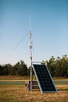
Because of the difficulty in obtaining distance to lightning with a single sensor, the only current reliable method for positioning lightning is through interconnected networks of spaced sensors covering an area of the Earth's surface using time-of-arrival differences between the sensors and/or crossed-bearings from different sensors. Several such national networks currently operating in the U.S. can provide the position of CG flashes but currently cannot reliably detect and position IC flashes. [15] There are a few small area networks (such as Kennedy Space Center's LDAR network, one of whose sensors is pictured at the top of this article) that have VHF time of arrival systems and can detect and position IC flashes. These are called lightning mapper arrays. They typically cover a circle 30–40 miles in diameter.
See also
References
- ↑ "Instrument: Lightning Mapping Array (LMA) | Global Hydrometeorology Resource Center (GHRC)". ghrc.nsstc.nasa.gov. Retrieved 2022-08-29.
- ↑ Richard Kithil (2006). "An Overview of Lightning Detection Equipment". National Lightning Safety Institute. Retrieved 2006-07-07.
- ↑ Brook, M.; N. Kitagawa (1960). "Electric-Field Changes and the Design of Lightning-Flash Counters". Journal of Geophysical Research. 65 (7): 1927–1930. Bibcode:1960JGR....65.1927B. doi:10.1029/JZ065i007p01927. Archived from the original on 2011-06-06. Retrieved 2009-07-14.
- 1 2 MacGorman, Donald R.; Rust, W. David (1998). The Electrical Nature of Storms. Oxford University Press, NY. ISBN 978-0-19-507337-9.
- 1 2 Williams, Earle R. (1995). "Meteorological aspects of thunderstorms". In Volland, Hans (ed.). Handbook of Atmospheric Electrodynamics, Vol. 1. CRC Press, Boca Raton. ISBN 978-0-8493-8647-3.
- 1 2 Williams, Earle R. (1985). "Large scale charge separation in thunderclouds". Journal of Geophysical Research. 90 (D4): 6013. Bibcode:1985JGR....90.6013W. doi:10.1029/jd090id04p06013. Archived from the original on 2011-06-06. Retrieved 2009-07-14.
- ↑ Yoshida, Satoru; Takeshi Morimoto; Tomoo Ushio & ZenIchiro Kawasaki (2009). "A fifth-power relationship for lightning activity from Tropical Rainfall Measuring Mission satellite observations". Journal of Geophysical Research. 114 (D9): D09104. Bibcode:2009JGRD..114.9104Y. doi:10.1029/2008jd010370. Archived from the original on 2011-06-06. Retrieved 2009-07-14.
- ↑ Vonnegut, Bernard; Moore, C.B. (1957). "Electrical activity associated with the Blackwell-Udall tornado". Journal of Meteorology. 14 (3): 284–285. Bibcode:1957JAtS...14..284M. doi:10.1175/1520-0469(1957)014<0284:EAAWTB>2.0.CO;2.
- ↑ Vonnegut, Bernard; James R. Weyer (1966-09-09). "Luminous phenomena in nocturnal tornadoes". Science. 153 (3741): 1213–1220. Bibcode:1966Sci...153.1213V. doi:10.1126/science.153.3741.1213. PMID 17754241.
- ↑ Rutledge, S.A.; E.R. Williams; T.D. Kennan (1992). "The down under Doppler and electricity experiment (DUNDEE): Overview and preliminary results". Bulletin of the American Meteorological Society. 73 (1): 3–16. Bibcode:1992BAMS...73....3R. doi:10.1175/1520-0477(1992)073<0003:TDUDAE>2.0.CO;2.
- 1 2 Uman, Martin A. (1987). The Lightning Discharge. Academic Press, N.Y. ISBN 978-0-12-708350-6.
- ↑ WX-500 Stormscope Series II Weather Mapping Sensor User's Guide (PDF). BF Goodrich Avionics Systems, Inc. 1997. pp. 4–2, 4–7. Archived from the original (PDF) on 2008-08-21.
- ↑ Golde, Rudolf H. (1977). Lightning. Vol. 1. New York: Academic Press. p. 368. ISBN 978-0-12-287801-5.
- ↑ Volland, H. (ed): "Handbook of Atmospheric Electrodynamics", CRC Press, Boca Raton, 1995
- ↑ Murphy Martin J.; Demetriades, Nicholas W.S.; Cummins, Kenneth L.; Ronald L. Holle (2007). Cloud Lightning from the U.S. National Lightning Detection Network (PDF). International Commission on Atmospheric Electricity, 13th International Conference on Atmospheric Electricity, Beijing.
External links
- Vaisala Lightning Detection Archived 2016-03-07 at the Wayback Machine from Vaisala
- Recent North American lightning activity from StrikestarUS
- Recent North American lightning activity Archived 2006-07-05 at the Wayback Machine from Environment Canada
- Lightning detection guide (PDF) from the U.S. NOAA
- Lightning origin and research on detection from space from NASA
- Australian national storm tracker Archived 2008-12-16 at the Wayback Machine from Weatherzone Australia
- European Cooperation for Lightning Detection
- WWLLN World Wide Lightning Location Network
- Venezuela Lightning Network (VLN)
- Live world detection map (blitzortung.org)
- Experimenter's Lightning Detector
- Echte 3D-Blitzortung inkl. Höhenangabe der Wolkeblitze